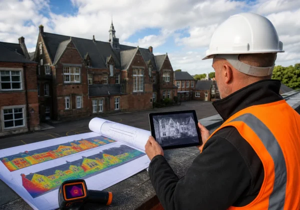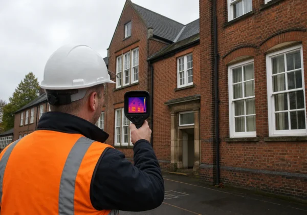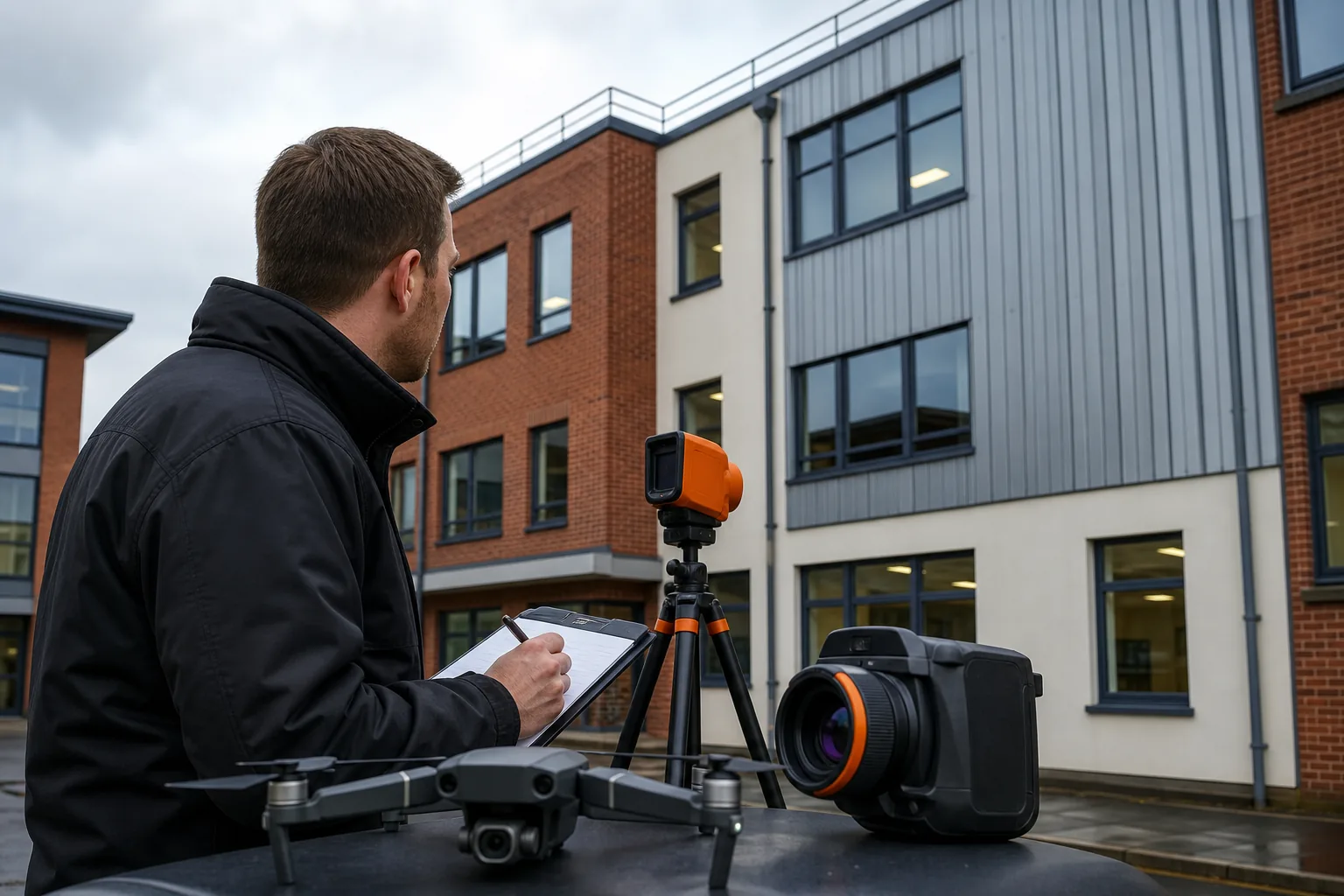
A thermal camera can show what the naked eye can’t see, but a colour image alone isn’t a diagnosis. Reliable building envelope thermal imaging starts with sound survey planning, suitable weather, correct camera settings and careful checks on site.
Use the following process to decide when a quick handheld scan is enough and when you need a managed inspection. Visual Perspectives Limited carries out independent drone-based surveys for UK estates, quickly, precise, and detailed.
1. Visual Perspectives Limited
Start by setting the survey goal before choosing the camera or access method. Visual Perspectives Limited provides managed drone-based aerial inspections for roofs, façades and wider building envelope checks across the UK.
We begin by defining the question. Is the survey looking for missing insulation, cold bridging, air leakage, moisture risk or general condition? A clear question shapes the flight plan and the final report. It also stops a long list of colourful images becoming a costly guessing exercise.
Visual Perspectives Limited has worked in commercial inspection since 2013. The company is a CAA authorised drone operator and works independently of installers. That independence matters when survey findings may affect a retrofit plan, a maintenance budget or a funding application such as PSDS Phase 4.
A managed drone survey suits large façades, high roofs, schools, NHS estates and housing portfolios. It can capture areas that would otherwise need ladders, scaffolding or a cherry picker. High-resolution thermal data can also be paired with 3D mapping, which helps teams locate a defect on the building rather than on an isolated image.
For a small internal check, a handheld thermal imager may be enough.
Step 2: Choose Suitable Conditions, Access and Equipment
Good building envelope thermal imaging best practices begin before anyone reaches the site. Plan the weather, access route, building use and equipment settings together.
Thermal contrast is the first test. The inside and outside of the envelope need a useful temperature difference for heat-loss paths to stand out. Avoid scans after strong sunshine has heated one elevation, unless solar loading is part of the investigation. Reflections from glass and metal can also mislead the camera.
Record the weather at the start and end of the survey. Note wind, rain, cloud cover, recent heating changes and the time of day. Keep the same details in the report. They help another surveyor judge whether a pattern is likely to be a defect or simply a short-term surface effect.
Set emissivity for the surface being measured. Emissivity describes how well a material emits infrared energy. Brick, render, glass, metal cladding and painted surfaces will not behave in the same way. A wrong setting can skew the apparent temperature, even when the camera itself is working correctly.
For formal work, select a calibrated thermal camera with suitable resolution and temperature accuracy. Visual Perspectives Limited’s managed drone inspections use a camera calibrated to 0.1°C accuracy, adjust emissivity for façade materials and plan GPS-stabilised flights between 30 and 150 metres where site conditions allow.
Check access before the survey. A drone may reduce work at height, but it doesn’t remove the need for a risk assessment, airspace checks, safe launch areas and permission from the site owner. For equipment details, see our Survey Equipment | Drones and Thermal Cameras page while building the scope.
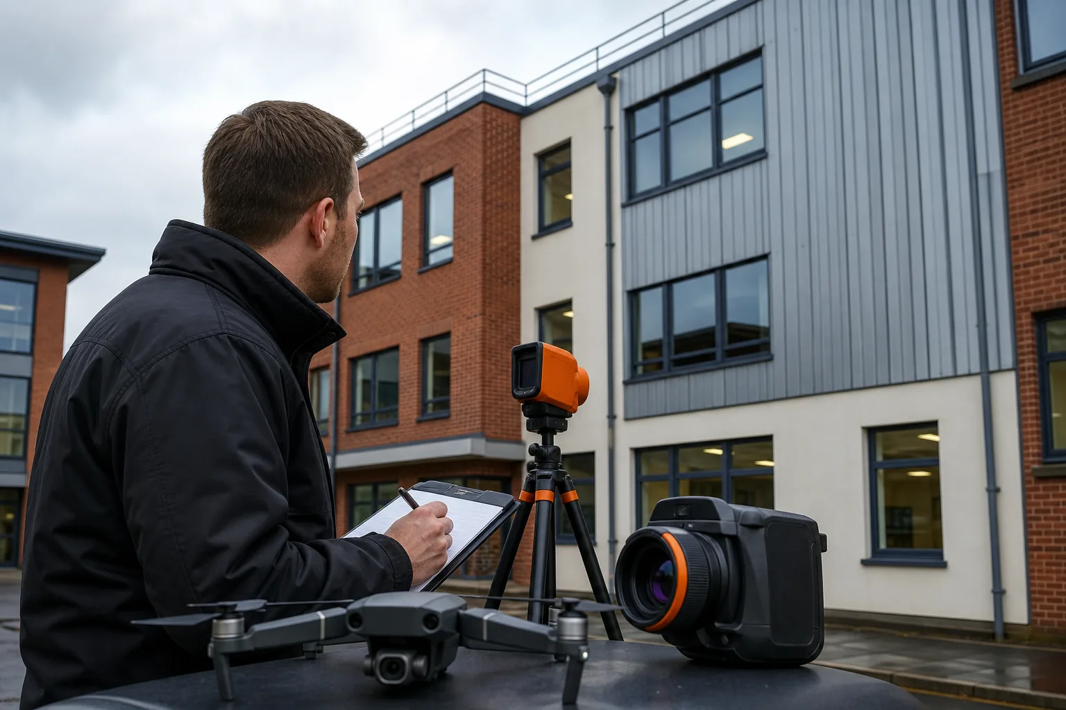
A handheld device remains useful for a room, a suspected outlet leak or a small wall section. Treat it as a screening tool unless the operator can support the readings with a repeatable method, site notes and a clear report.
By now you should have a written survey question, a safe access plan, suitable weather and recorded camera settings. You’ll be in good hands when every reading has enough context to be checked later.
Step 3: Scan the Exterior for Heat Loss and Envelope Defects
Use the exterior scan to map patterns across the envelope, then mark areas that need closer review. Building envelope thermal imaging is strongest when you compare similar materials and repeated details.
Work in a planned sequence. Start with a broad scan of each elevation. Then move closer to window heads, corners, parapets, roof edges, service penetrations and changes in wall construction. Keep the camera angle as close to perpendicular as the site allows. Oblique views can make a small area appear larger or change the effect of reflected radiation.
Look for patterns rather than isolated bright or dark pixels. A vertical cold strip may follow a structural junction. Repeated cold patches below windows may point to a design detail or air movement. A warm area on a roof may relate to moisture, trapped heat or plant equipment. The thermal image tells you where to ask questions, not the final cause.
Pair each thermal frame with a visible-light image. Add a location reference, elevation name and image number. On a large estate, this simple record saves time when a surveyor later needs to find one defect among hundreds of images.
During a commercial roof inspection, a useful finding is rarely “the roof is cold”. It is more useful to state that a repeated thermal pattern follows a roof zone, give its location and explain what needs checking next. That wording supports a maintenance task rather than a vague energy claim.
Finish each elevation before moving on. Gaps in coverage are hard to spot once the drone has landed, especially on a complex school or hospital estate. You’ll be in good hands when image position and visible condition are recorded together.
Step 4: Investigate Internal Heat Loss Paths and Air Leakage
Internal checks help confirm how heat moves through the building. They are a key part of building envelope thermal imaging because exterior patterns alone rarely prove air leakage.
Set the heating system to its normal operating state before the survey, where the building manager permits this. Record rooms that are unheated, closed or affected by local equipment. A vacant classroom, a plant room and a busy ward will produce different thermal conditions.
Scan wall-to-floor junctions, window frames, door seals, service penetrations, ceiling edges and electrical outlets. Cold patches around outlets can indicate air infiltration, especially on an exposed wall. Check the surrounding surface first, then compare the suspected leak with a similar outlet on an internal partition.
Pay close attention to thermal bridge s. A thermal bridge is a route where heat crosses the envelope more easily than through the surrounding construction. Common locations include slab edges, balcony connections, steel frames and corners. A cold bridge can increase surface condensation risk, but the camera cannot confirm moisture on its own.
Keep the camera square to the surface and avoid placing your hand near the suspected area before capture. Human contact changes the surface temperature. Furniture can also hide a defect, while curtains may alter airflow around a window.
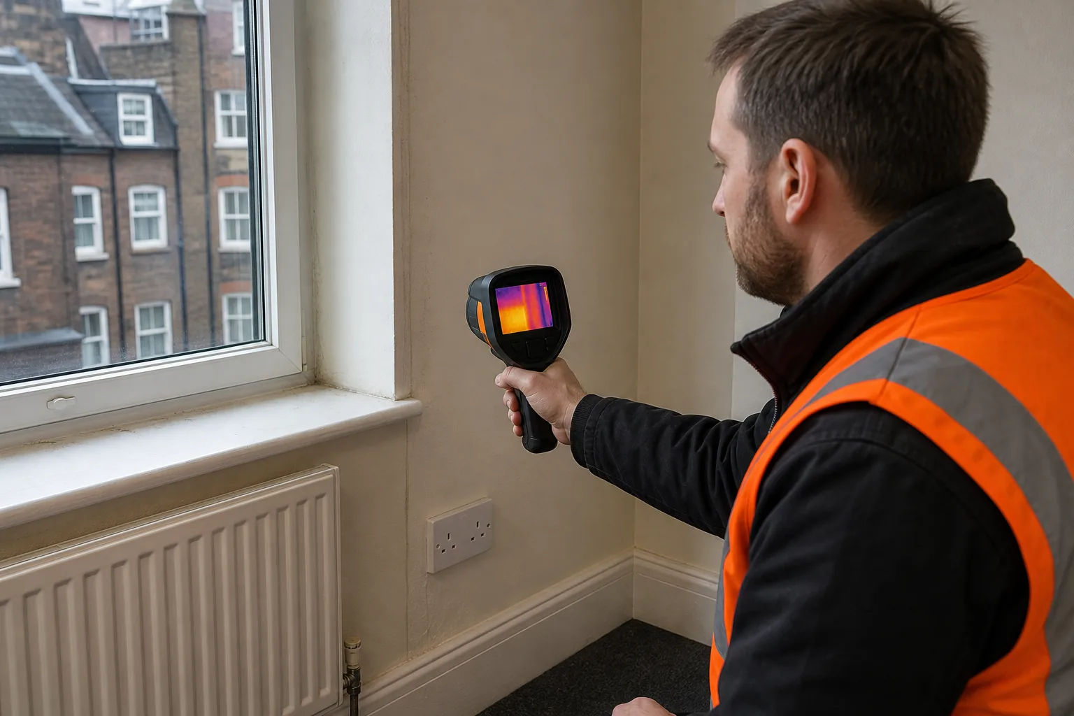
Use a handheld scan for a focused investigation. Use a managed drone survey when internal access is limited or the suspected fault covers a large external area. Visual Perspectives Limited can link internal observations with aerial roof and façade data, which gives the project team a clearer route from symptom to inspection task.
The thermal imaging moisture detection guidance explains why moisture-related patterns need careful data collection, verification and reporting rather than diagnosis from colour alone. These details matter when a report may guide retrofit work.
By now you should have paired internal patterns with room use, building orientation and visible construction details. You’ll be in good hands when you treat air leakage as a hypothesis to test, not a conclusion from one blue patch.
Step 5: Verify Anomalies Before Diagnosing the Cause
Verification stops a thermal anomaly becoming an incorrect repair recommendation. This is where careful building envelope thermal imaging separates useful evidence from guesswork.
First, repeat the image from a different angle or distance. Then compare the area with a nearby section built from the same material. Check the visible-light image for shading, dirt, damage, open vents, pipework or plant that could explain the pattern.
Ask what changed before the scan. Was the heating switched on? Did rain fall on one elevation? Has insulation been added in only part of the building? Was a room recently ventilated? These details can explain a temperature difference without proving a defect.
Use other inspection methods where needed. A suitable damp-assessment method can support a damp investigation. A cavity inspection method may help inspect a cavity. A direct leakage test can assess leakage more directly. A thermal camera points to the next test; it does not replace that test.
For each anomaly, record a confidence level and a recommended follow-up. “Confirm insulation continuity at wall junction” is stronger than “insulation failure”. “Inspect roof build-up for moisture” is safer than stating that moisture is present without supporting evidence.
Repeat scans are useful when a project is testing a repair. Use the same viewpoint, settings and weather notes where possible. The comparison then shows whether the thermal pattern changed after work.
Step 6: Report Findings and Prioritise Decarbonisation Action
A good report turns thermal images into decisions. It should help an asset manager decide what to inspect next, what to repair first and what needs a wider retrofit review.
Give each finding a unique reference. Include the location, image pair, surface type, observed pattern, likely explanations and recommended next action. Add the survey date and weather record. State the limits of the inspection, including areas that were inaccessible or affected by reflections.
Group findings by building element rather than by image number. A project team may need one action for roof insulation, another for window seals and a third for a cavity wall investigation. This format fits better into a condition survey or an estate asset plan.
Prioritise by risk and consequence. A defect that threatens water ingress may need attention before a small heat-loss pattern. A repeated cold bridge across occupied accommodation may deserve early design review because it can affect comfort and condensation risk. Link each action to the person who can progress it.
For public-sector estates, use the evidence to support a fabric-first retrofit sequence. Review the envelope before sizing new heating plant. If the building loses heat through failed insulation or uncontrolled air paths, a plant upgrade may not solve the underlying problem.
Visual Perspectives Limited provides independent thermal imaging, drone roof surveys and building diagnostics across education, healthcare, housing and commercial property. We can help turn survey records into a prioritised evidence pack for maintenance or decarbonisation planning.
A useful handover includes marked-up elevations, thermal and visible images, a defect schedule and a short executive summary. Keep the technical detail available for the surveyor, but make the next action clear for the estates manager. The right report earns its place when someone can use it at the next project meeting.
FAQ: Building Envelope Thermal Imaging
What is the best weather for a thermal building survey?
The best conditions provide a clear temperature difference without strong solar heating, rain or excessive wind. Scan when the building is in its normal operating state, record weather conditions and avoid comparing surfaces affected by different sun exposure. These controls make building envelope thermal imaging results easier to interpret.
Can a handheld thermal camera find heat loss?
Yes, a handheld thermal camera can find areas that need investigation, such as cold patches around outlets or window edges. It cannot prove the cause by itself. For formal reporting across a large façade or roof, use a repeatable method with calibrated equipment, correct emissivity settings and location records.
What does a cold patch mean on a thermal image?
A cold patch may indicate air leakage, missing insulation, a thermal bridge, moisture-related cooling or a surface effect. It does not identify the cause on its own. Compare the patch with similar materials, check the visible image and verify it with another inspection method before specifying repairs.
Is drone thermal imaging suitable for public-sector estates?
Drone thermal imaging suits large roofs, façades and hard-to-reach areas across schools, NHS buildings, housing and government estates. It still needs a flight risk assessment, suitable weather, safe access controls and a qualified operator. A managed inspection can reduce work at height while producing location-based evidence for asset planning.
Does thermal imaging prove that a building is damp?
No, thermal imaging does not prove dampness. Moisture can change surface temperature, but the same pattern may have another cause. Use the thermal image to target follow-up checks with supplementary measurements, visual inspection or opening-up where justified. This approach reduces the risk of an incorrect damp diagnosis.
Conclusion
Use thermal imaging as a measured inspection process, not a hunt for dramatic colours. Start with the survey question, control the conditions, verify anomalies and report each finding with a clear next action. Visual Perspectives Limited provides independent drone and building thermography surveys across the UK, giving estates teams better evidence for maintenance and decarbonisation decisions.