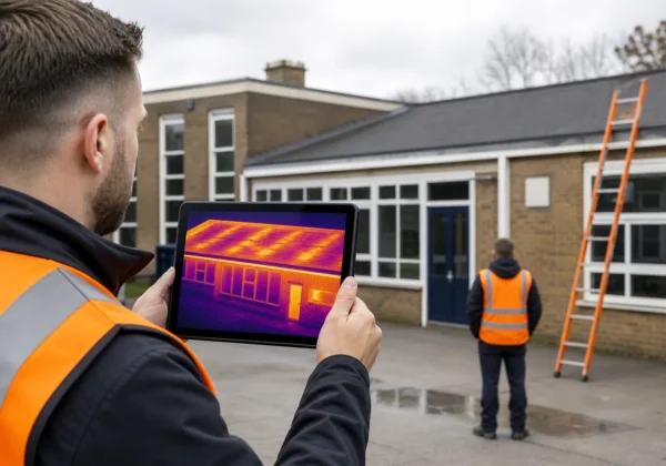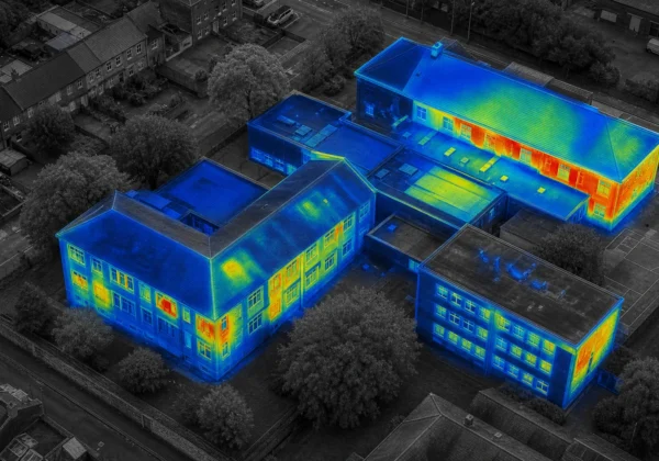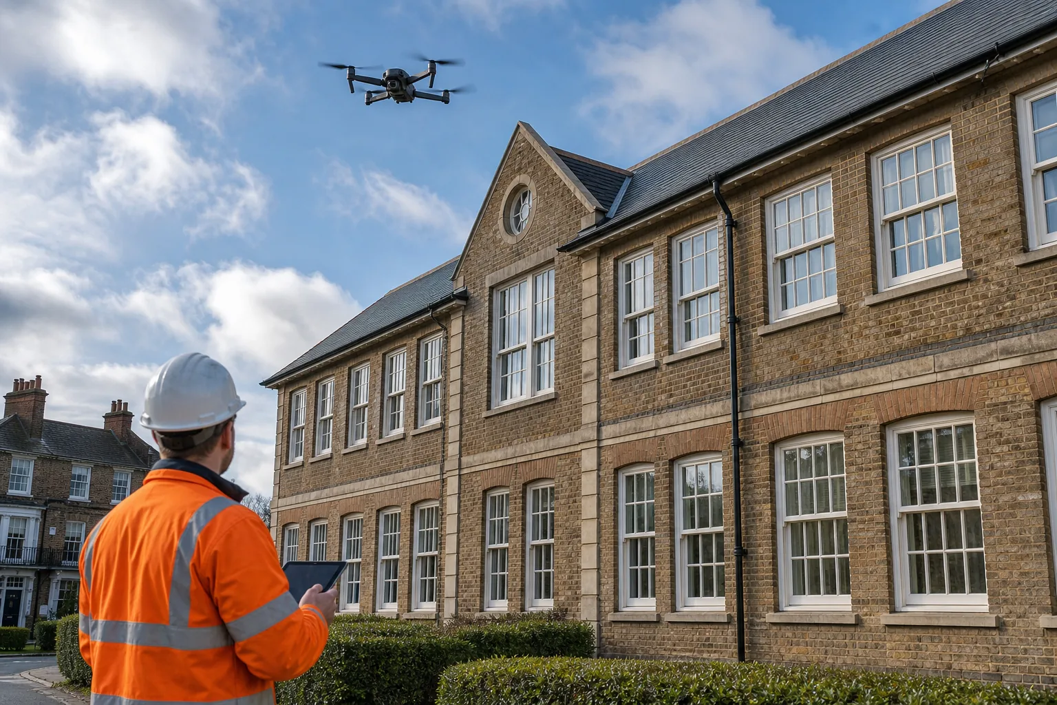
Heat loss is often blamed on insulation before anyone has checked the building properly. Building fabric heat loss analysis gives estate teams a clearer route from visible defects to sound retrofit decisions. The method below combines records, envelope inspection, thermal imaging and validation, so you can act on evidence rather than guesswork.
Step 1: Define the Building, Scope and Evidence Required
Start building fabric heat loss analysis with a clear question: what must the survey prove? A school may need evidence of cold classrooms. An NHS estate may need to explain high heat demand across several blocks. A housing association may need to check failed cavity insulation before planning external wall insulation.
Write the scope before anyone visits site. Record the building address, use, age, construction type and floor area if known. Mark extensions, roof forms, occupied rooms and areas with known damp or comfort complaints. Add the purpose of the work, such as retrofit planning, a condition survey, PSDS Phase 4 preparation or a maintenance decision.
Gather existing evidence next. Ask for drawings, energy bills, EPC information, previous surveys, heating records and reports of leaks. Note where records conflict. Old drawings can show a cavity wall that was later filled, while maintenance notes may point to a roof repair that never solved the problem.
Set the evidence standard for each finding. A suspected cold bridge needs a thermal image and a site note. A claim about missing insulation may need intrusive testing or a specialist insulation check. A roof defect may need a drone view because the relevant detail cannot be seen safely from the ground.
For a useful explanation of the wider survey process, to building envelope heat loss diagnostics. It helps teams connect thermal patterns with inspection records rather than treating each image as a stand-alone result.
Agree the report format at this stage. Public estate teams usually need marked-up elevations, image references, defect descriptions, risk ratings and actions that a project manager can cost. Visual Perspectives Limited can combine high-resolution 3D mapping with thermal imaging from drones, giving you quickly, precise, and detailed site evidence across large or difficult buildings.
By now you should have a written scope, a document pack and a list of questions the inspection must answer. You’ll be in good hands when the field team knows what decision the evidence must support.
Step 2: Inspect the Building Envelope and Record Heat-Loss Risks
Good building fabric heat loss analysis starts with a careful envelope inspection, not with the camera. Walk the building in a consistent route. Record what the walls, roof, windows, doors and junctions are doing before you interpret temperature patterns.
Look for signs that point to heat loss or moisture:
- Gaps around window and door frames.
- Cracked sealant at façade junctions.
- Missing or damaged roof insulation.
- Cold corners beside columns and floor slabs.
- Discoloured finishes that may indicate damp.
- Blocked vents or altered ventilation paths.
- Uneven repairs across otherwise similar elevations.
Photograph each issue in context. A close image shows the defect, while a wider view shows its position on the elevation. Give every observation a reference number that will appear in the thermal report. This small step saves time when a surveyor, energy manager and contractor review the findings together.
Separate heat loss from water-related cooling. Wet materials can appear cooler than dry areas, but a cool patch does not prove missing insulation. Check gutters, outlets, roof falls, plumbing routes and recent weather. On a flat roof, a damp survey may be needed before anyone specifies additional insulation.
Use safe access methods. A drone roof survey can inspect high façades, parapets and roof edges without putting staff on fragile surfaces. It also gives a broad view of repeating defects across an elevation. Visual Perspectives Limited provides managed drone inspections across the UK, with high-resolution imagery that shows what the naked eye can’t see from ground level.
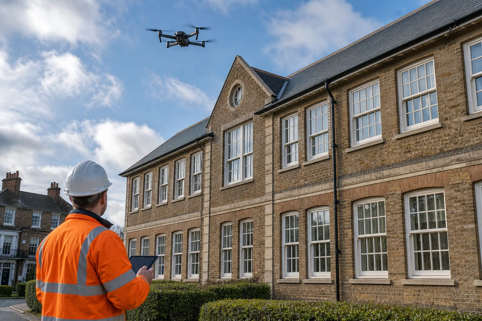
For larger estates, record findings in a schedule rather than relying on memory. Include location, defect type, likely cause, confidence level and suggested next test. A low-confidence observation should lead to more checking, not an expensive retrofit decision.
By now you should have a defect map that explains where heat may escape and where moisture could distort the results. That map sets the flight plan and camera brief for the next step.
Step 3: Plan and Capture Thermal Imaging Correctly
Thermal imaging makes building fabric heat loss analysis useful only when the images are captured under suitable conditions. An infrared camera records surface temperature. It does not directly measure insulation thickness, air leakage or energy use.
Plan the survey around a useful temperature difference between inside and outside. Avoid periods when strong sunlight has warmed one elevation, because solar gain can hide or mimic heat loss. Rain can also change surface temperatures and create misleading patterns. Record weather, time, wind, cloud cover and building operating conditions in the field notes.
Check the building before scanning. Internal heating should be operating in the areas under review, unless the survey brief says otherwise. Note open windows, unused rooms, portable heaters and doors that have been left open. These details can explain a temperature anomaly later.
Set a repeatable capture method. Keep the camera angle as square to the surface as access allows. Capture each elevation at a suitable distance, then take closer images of suspected defects. Pair every infrared image with a visual image. Without that pair, a roof outlet, sign bracket or patch repair can be hard to identify.
Control the camera settings and record them. Emissivity describes how a surface emits infrared energy. Reflected temperature describes infrared energy coming from nearby surfaces. Glazed areas, polished metal and wet finishes need care because their readings may not represent the fabric behind them.
Drone-based thermography adds a useful view of tall elevations and roofs. It can cover areas that would need costly access equipment, while 3D mapping gives each image a place on the building model. This matters when a project team needs to return to one parapet detail or compare matching elevations.
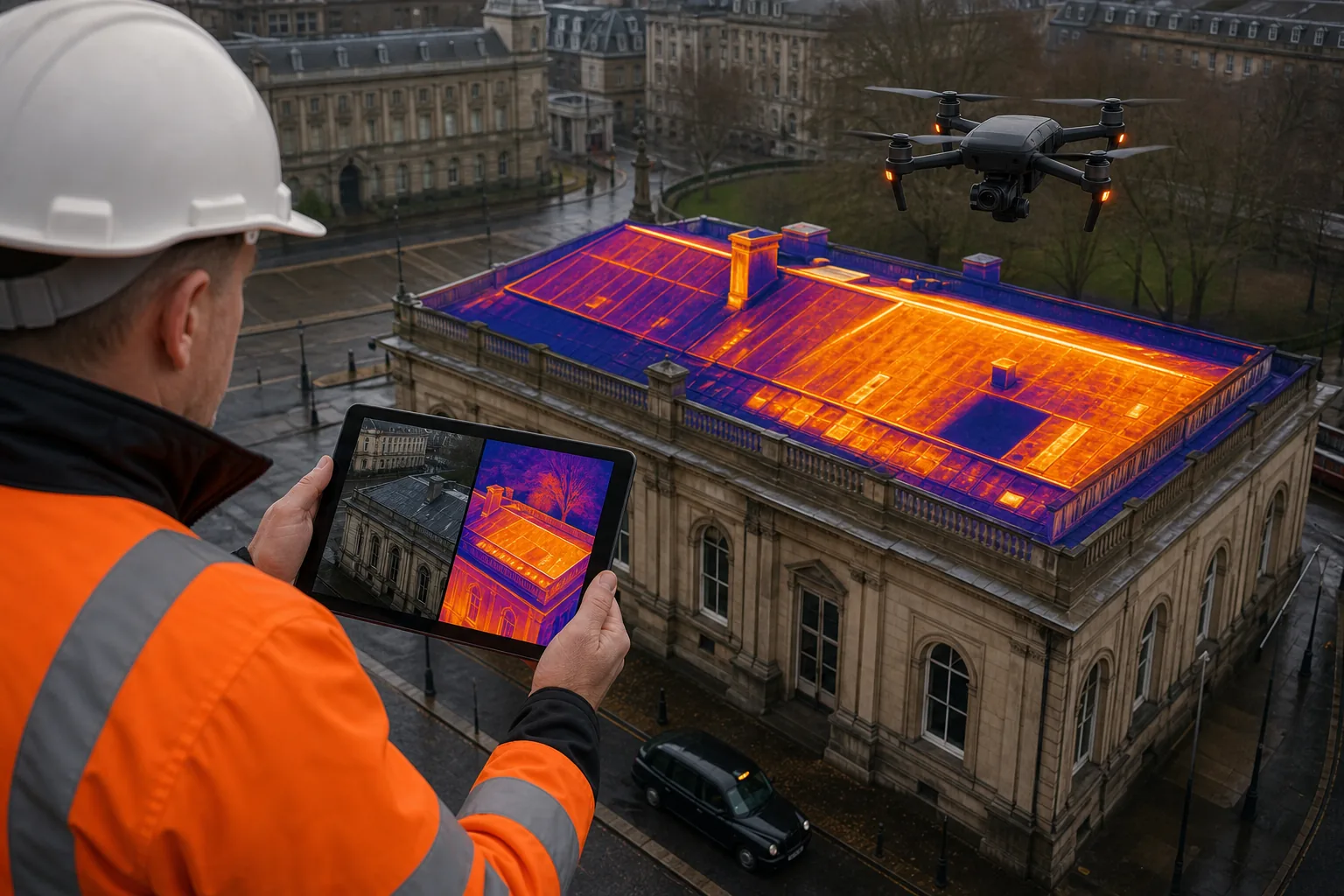
Thermal imaging must be interpreted with care. A warm strip may show heat escaping through a junction, but it may also show a pipe, a heater, a sunlit surface or a change in material. Mark the pattern, state the likely cause and give a confidence rating.
Visual Perspectives Limited carries out thermal imaging and 3D mapping for public buildings, commercial property and wider estates. We capture survey data quickly, precise, and detailed, then link the findings to locations that a maintenance team can identify.
By now you should have correctly captured thermal and visual images with matching location data. You’ll be in good hands when every unusual pattern has context before it reaches the report.
Step 4: Analyse Heat-Loss Patterns and Validate the Findings
Analysis is where building fabric heat loss analysis moves from coloured images to a defensible finding. Review each thermal pattern beside its visual image, elevation reference and site note. Then compare it with similar parts of the building.
Look for patterns that repeat. A cold line at every floor slab may indicate a thermal bridge, which is a part of the structure that conducts heat more readily than the surrounding fabric. A cold patch beside only one window may point to a local seal failure. A broad cool roof area may relate to moisture, insulation or surface exposure.
Test each finding against other evidence. Compare internal and external images where possible. Check whether the pattern matches construction drawings. Review heating controls and room use. Ask whether the area was occupied, ventilated or affected by a nearby heat source during capture.
Do not turn a thermal image into a precise energy saving figure without a suitable calculation model. Thermal imaging shows a condition at the time of capture. It supports diagnosis, but it does not replace heat-loss calculations, air leakage testing or intrusive investigation where those are required. Teams planning a survey should also follow building envelope thermal imaging best practices so that capture conditions, image interpretation and reporting remain consistent.
Use a simple validation record for each issue:
- Observed pattern and exact location.
- Likely mechanism, such as bridging, air leakage or moisture.
- Supporting evidence from the visual survey.
- Confidence level and any limits.
- Next test or action.
If the evidence is weak, say so. An honest recommendation for further testing is more useful than a confident diagnosis built on one image. By now you should have findings that a surveyor can challenge, verify and pass into a project brief.
Step 5: Convert the Analysis into a Prioritised Retrofit and Maintenance Plan
The final stage of building fabric heat loss analysis is a decision plan. Put each finding into a clear order based on risk, cost, disruption, confidence and likely effect on the building.
Start with defects that can damage the fabric or distort later retrofit work. A leaking roof should not wait behind a speculative insulation upgrade. Failed sealant should be repaired before a façade system is designed. Damp should be investigated before insulation is added to the affected area.
Then group lower-risk opportunities by building element. A plan may contain separate work packages for roof insulation, window seals, cavity wall investigation, thermal bridge treatment and ventilation changes. Each package needs an owner, a next action and a route to verification.
Use the findings to shape, rather than dictate, a decarbonisation plan. Fabric improvements can reduce heat demand and improve comfort, but the balance between fabric work and heating-system change needs a building-by-building decision. Read this wider discussion of fabric-first retrofit.
For a public estate, score each recommendation against:
- Health, safety or building damage risk.
- Effect on occupied rooms and service continuity.
- Readiness of the design information.
- Compatibility with planned heating changes.
- Need for surveys under PAS 2035 or another project requirement.
- Ease of checking the work after completion.
Do not assume every building needs the same answer. A cavity wall repair may suit one school block. A solid-wall hospital wing may need a different sequence. A roof with moisture damage may need repair and drying before any insulation decision.
Set a verification point after the work. Repeat thermal imaging under comparable conditions where possible. Review maintenance records and occupant complaints. Check whether the original defect has changed, rather than simply recording that a contractor attended.
Visual Perspectives Limited can provide independent thermal imaging, drone inspection and building diagnostics to support this handover from survey to action. We work with asset managers, surveyors and decarbonisation teams across the UK, so the evidence can sit alongside the wider estate plan. That keeps the next decision clear, and you’ll be in good hands.
Frequently Asked Questions
What is building fabric heat loss analysis?
Building fabric heat loss analysis is a structured review of how heat escapes through a building’s envelope. It combines records, visual inspection, thermal imaging and validation. The result should identify likely defects, explain confidence in each finding and set out suitable next actions. It is diagnostic evidence, not a replacement for detailed design calculations.
Can thermal imaging prove missing insulation?
Thermal imaging can indicate unusual heat patterns that may relate to missing or uneven insulation, but it cannot prove the cause on its own. Surface temperature is affected by weather, moisture, air movement, heating and materials. Confirm important findings with drawings, intrusive checks, air testing or another suitable investigation before specifying work.
When is the best time to carry out a heat loss survey?
The best time is when the building has a useful indoor to outdoor temperature difference and the envelope is not being strongly affected by sun or rain. The heating should operate as agreed in the survey brief. Your survey team should record weather and building conditions so the results can be judged fairly.
Why use a drone for building heat loss analysis?
A drone can inspect high façades, roof edges and large roof areas without putting people onto difficult or fragile surfaces. It can also capture a consistent view across a large estate. Drone data does not remove the need for ground checks, but it can improve access to areas that are hard to inspect safely.
Does heat loss analysis replace a condition survey?
No. Heat loss analysis focuses on thermal performance and related envelope defects. A condition survey covers a wider range of building elements and repair needs. The two surveys can support each other. Thermal findings may help target further checks, while condition records provide the context needed to interpret unusual temperature patterns.
Conclusion
Use building fabric heat loss analysis to establish facts before committing public funds to retrofit. Define the question, inspect the envelope, capture thermal images under controlled conditions and validate every important pattern. Visual Perspectives Limited provides independent drone and thermal inspection services across the UK. Start by selecting one building, gathering its records and commissioning evidence that your project team can act on.