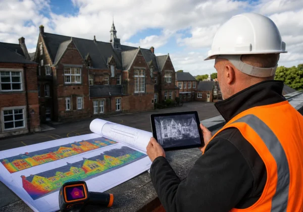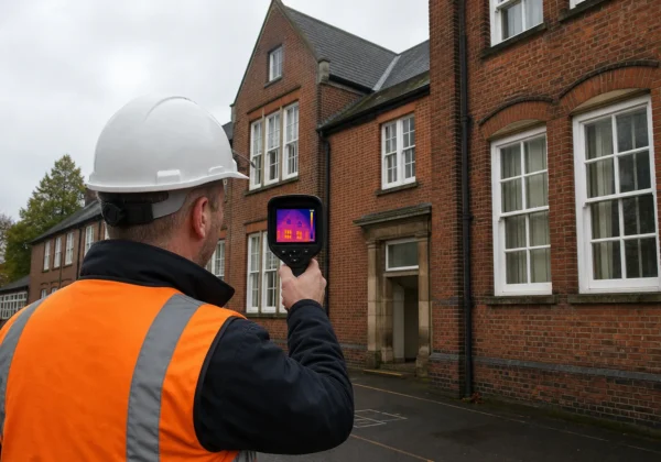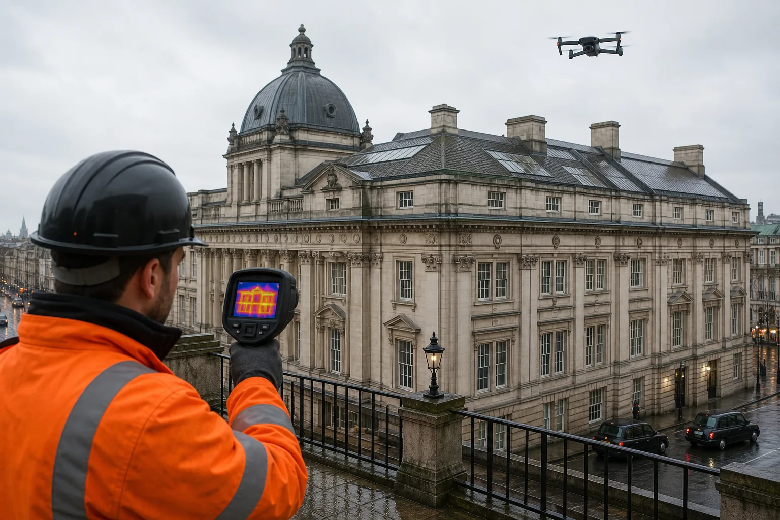
Heat can leave a building through a roof, wall, window or tiny gap that looks harmless. A building envelope heat loss inspection finds those weak points by combining thermal imaging with air leakage tests and site evidence. The reliable route is layered: define the risks, prepare the building, scan the envelope, verify defects, then link each finding to a repair.
Step 1: Define the Inspection Scope and Likely Heat-Loss Paths
A good building envelope heat loss inspection starts with a clear scope. Do not begin with the camera. Begin with the building record, the people who use the site and the decisions the survey must support.
For a school estate, you may need evidence before a retrofit scheme. For an NHS estate, the priority may be comfort complaints, damp risk or a failing roof. A housing association may need repeatable results across many properties. Write the purpose down before anyone visits.
Build the site record
Collect the address, building age, construction type and floor area. Add the heating system, recent refurbishment details and known defects. Record which rooms are occupied and note any areas that cannot be entered.
PAS 2035 style records should also cover external condition, damp or mould observations, cavity depth where known, measurements, risk forms and signed compliance records. The exact record should match the project brief, but missing basic data can make later comparisons weak.
Use the building envelope diagnostic checklist to structure the first review. It helps you work through roofs, walls, windows, foundations, moisture and air leakage before the survey team arrives.
Map the likely heat-loss paths
Heat moves through the envelope in three main ways. Conduction passes through solid materials. Convection moves with air. Radiation transfers heat between surfaces. In practice, these effects overlap.
- A missing insulation section can conduct heat faster than the surrounding wall.
- A gap around a door frame can let cold air move into the room.
- A steel beam or concrete slab can form a thermal bridge, which is a fast route through the insulation layer.
- A roof penetration may allow air or water to reach a hidden part of the construction.
- An outlet box, service duct or window reveal can create a small but repeated cold spot.
Mark these areas on a plan. Note roof edges, parapets, corners, junctions between walls and floors, window heads, door thresholds and plant penetrations. On larger sites, split the building into zones. Give each zone a reference code that will appear on photographs and the final report.
Keep supporting material with the survey record, and use infrared thermography to answer a defined inspection question.
By now you should have a building plan, a defect history, a list of restricted areas and a reason for every inspection zone. You’ll be in good hands when the field work begins.
Step 2: Prepare the Building, Weather Conditions and Equipment
Preparation controls the quality of a building envelope heat loss inspection. Thermal patterns depend on the temperature difference across the envelope, while air leakage tests depend on the building being set up correctly.
Check the weather window
Plan the scan when indoor and outdoor temperatures differ enough to reveal weak points. Keep conditions as stable as possible during the survey. Strong wind can disturb surface temperatures and may hide or mimic air leakage.
Sun can also heat one face of a building while leaving another in shade. Record the direction of the sun and the time of each image. Avoid comparing a sunlit wall with a shaded wall as if they had the same conditions.
For a roof survey, complete a pre-scan examination. Look for access points, hot plant, flashing, penetrations and hazards. A flat roof may show warm areas caused by trapped moisture, but a heat pattern alone does not prove the moisture source.
Prepare the building
Walk the interior before testing. Check windows, doors, ventilation openings, combustion appliances, extract fans, flues, dampers and plumbing traps. Agree who can isolate mechanical equipment. Do not disable life-safety systems without the right authorisation.
For pressure testing, close and latch openings in the envelope. Seal intentional outdoor air openings where the test method requires it. Open internal doors so air can move through the test zone. Record anything that cannot be sealed.
Pressure testing is not a casual smoke check. A calibrated fan, pressure gauge and suitable frame are needed to measure airflow. The test team should also set out exclusion zones and confirm that the pressure will not damage equipment or disturb occupants.
Check the equipment
Use a thermal camera that can record images with measurement data, not only colour pictures. Check the lens, battery, focus and emissivity settings. Reflective metal can show reflected heat rather than its own surface temperature, so inspect it with care.
Keep a visible link between each thermal image and its ordinary photograph. Include a room code, elevation, direction and short defect note. For roof work, an aerial drone can cover large areas without putting a person on every roof section. Visual Perspectives Limited provides managed drone surveys with high-resolution 3D mapping and thermal imaging for this type of estate-wide work.
Before installation work begins, consider a pre-installation roof condition survey. Hidden moisture or saturation should be found before racking or other fixed equipment blocks access. Otherwise, later repairs may require removal and reinstallation work.
The winter building envelope diagnostics guide gives useful planning context for UK estates, where weather, access and heating patterns can change quickly.
By now you should have a signed risk assessment, a weather log, tested equipment and a prepared building. You’ll be in good hands when the first image is captured.
Step 3: Carry Out the Thermal Imaging Survey
Thermal imaging is the main screening tool in a building envelope heat loss inspection. It shows surface temperature patterns that the naked eye can’t see. It does not, on its own, prove why the pattern exists.
Scan the outside first
Start with a slow external walkaround when the building is under normal operation. Take broad images first. Then move closer to corners, window reveals, wall junctions, roof edges and penetrations.
Keep the camera square to the surface where possible. Oblique views can make a small area look larger or change the apparent temperature. Record the distance and viewing angle when a finding may need later verification.
Look for sharp temperature changes rather than isolated colours. A vertical cold band may point to missing insulation or a stud line. A bright strip beside a window may show heat leaving the room through a weak junction. A roof anomaly may relate to moisture, insulation, air movement or solar gain.
Scan the inside
Repeat the survey indoors. Compare the same wall from both sides where access allows. Check the corners first, then window and door edges, ceiling lines, floor junctions and service penetrations.
Pay close attention to repeated patterns. A cold patch beside every window suggests a design or installation detail. One cold patch beside one window may point to local damage. Outlet boxes can also show air movement behind the faceplate, but do not remove electrical covers unless a qualified person is responsible.
Use a normal photograph beside each thermal image. A colour scale without location information is hard to act on. A report should let a contractor find the defect without guessing which elevation or room was meant.
Choose the right survey method
An under-the-roof method can help find moisture or insulation changes from inside, though walls, plant and stored goods may block the view. An on-roof method gives close coverage but requires safe roof access. An improved vantage point can cover more roof area while keeping landmarks in view.
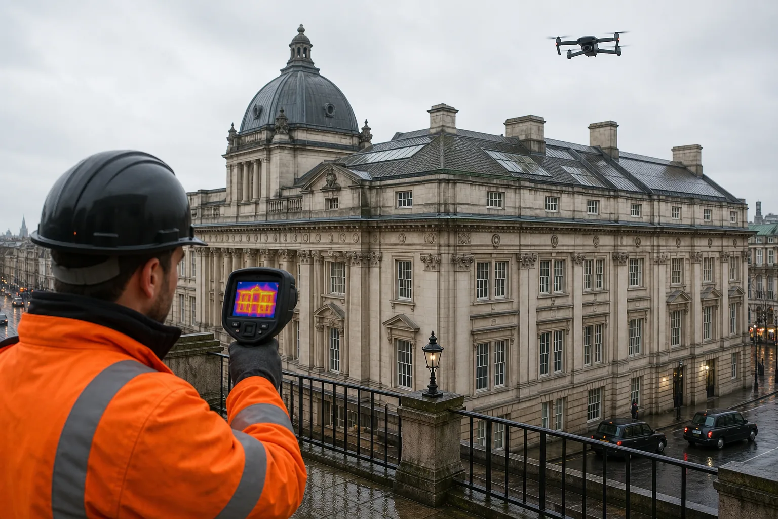
An aerial drone method can map a whole roof with a high-resolution thermal camera. It is useful for large public buildings, estates and roofs where access is difficult. Drone data still depends on stable conditions. Wind can disturb the result, and a thermal image cannot replace a roof inspection when the cause remains uncertain.
Temperature difference, written as ΔT, is the key quantitative measure used across these methods. A typical detection threshold cited for several roof methods is ΔT of 2 to 4°C. Treat that as a survey guide, not a universal pass or fail limit. Materials, weather, angle and moisture can change the result.
Visual Perspectives Limited combines thermal imaging with 3D mapping so the defect can be placed within a wider roof or façade record. The survey is quickly, precise, and detailed, but the report still needs human interpretation.
By now you should have paired thermal and ordinary images for each inspection zone, along with the weather conditions and ΔT notes. You’ll be in good hands when the findings move to verification.
Step 4: Verify Air Leakage with Pressure and Smoke Testing
Thermal imaging can show where air leakage may occur. A pressure test helps measure how much air the building loses. Smoke helps trace the path at a particular location.
Set up the pressure test
Fit the calibrated fan into a suitable door or opening. Confirm the test zone and record its volume or envelope area, depending on the reporting method. Close the openings agreed during preparation.
Run the test at controlled pressure levels. Take readings at more than one pressure where the method calls for it. A regression analysis can then help produce a more reliable leakage relationship instead of relying on one reading.
Pressure results should be tied to the building geometry and the owner’s target. A large building and a small building cannot be compared fairly from raw airflow alone. State the test conditions, equipment and limitations in the report.
Use smoke to trace the route
With the building under negative pressure, air is pulled in through gaps. Move a smoke wand along window frames, door seals, service penetrations, skirting lines and suspected joints. Watch the smoke path rather than the size of the visible plume.
Smoke is useful where infrared readings are unreliable. Reflective surfaces can confuse the camera. Small temperature differences may also hide a leak. Hot radiators and flues can dominate an image, while smoke may still show the direction of air movement.
Never use smoke near an active alarm, sensitive equipment or an unsafe combustion appliance without a written method and proper controls.
Read both tests together
Infrared imaging gives a qualitative location. Pressure testing gives a quantitative result. Smoke helps confirm the route. Used together, they can separate a cold surface caused by air movement from one caused by missing insulation.
Infrared thermography can support the assessment of leakage. That combination matters during commissioning because the visible defect and the total leakage rate answer different questions.
Do not promise that every visible cold line will affect the whole building’s leakage result. A small defect may matter to comfort in one room while making little difference to the total measurement. Record both effects.
By now you should have a leakage result, marked air paths and notes on any areas that could not be tested. You’ll be in good hands when each thermal pattern is checked against the construction.
Step 5: Interpret Thermal Patterns and Verify the Defect
Interpretation turns a thermal image into a building decision. A building envelope heat loss inspection should never label a coloured patch as a defect without checking the site conditions.
Ask what could cause the pattern
Start with the image record. Check the time, weather, surface direction, camera angle and nearby heat sources. Compare the suspect area with a similar unaffected area. Then compare inside and outside views.
Use the construction drawings where available. A wall that looks uneven may contain a structural frame. A roof stripe may follow a joist, drainage route or insulation joint. A cold corner may be a thermal bridge rather than a leak.
Moisture can also alter a surface temperature pattern. On a flat roof, a warm area after sunset may indicate wet insulation because water changes the way the roof stores heat. That finding needs physical or moisture verification before repair work is specified.
Use a verification ladder
- Confirm the thermal anomaly appears in more than one image or viewing angle.
- Compare the pattern with an ordinary photograph and the construction detail.
- Check for air movement with pressure and smoke testing where suitable.
- Use moisture measurement or a targeted opening when the cause remains uncertain.
- Ask a competent contractor to confirm the source before setting the repair scope.
This process keeps the report honest. It also stops a contractor from replacing sound insulation because a reflective surface produced a misleading image.
| Thermal pattern | Possible cause | Useful verification | Initial action |
|---|---|---|---|
| Cold line beside a window | Air leakage or weak reveal detail | Smoke test and internal check | Review seal, frame and insulation detail |
| Large roof area with delayed heat response | Possible trapped moisture | Moisture survey and roof inspection | Mark the area before any overlay or replacement |
| Repeated cold bands at wall joints | Thermal bridging or missing insulation | Drawings, internal scan and local opening | Model the junction before retrofit |
| Isolated cold spot at an outlet | Air path behind the electrical box | Smoke test by a competent person | Seal the surrounding air barrier safely |
| Hot patch near plant or roof penetration | Heat source, flashing detail or moisture effect | Site inspection and temperature log | Separate plant heat from envelope defects |
Write findings that a project team can use
Each finding should have a location code, image pair, measured condition and confidence level. State what is known. Then state what still needs checking.
Give the defect a consequence that fits the evidence. It may affect comfort, moisture risk, maintenance access or retrofit performance. Do not turn a thermal anomaly into a predicted energy saving unless the building model supports that claim.
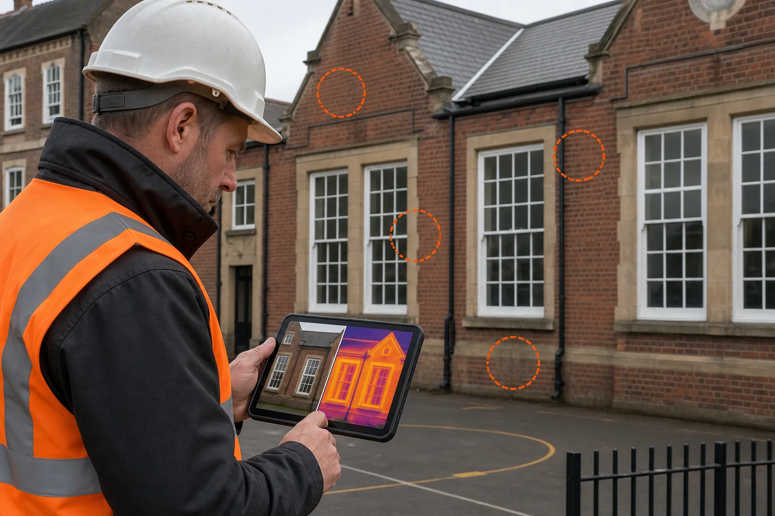
By now you should have verified findings with clear limits. You’ll be in good hands when the report becomes a repair plan.
Step 6: Turn Findings into a Prioritised Repair and Decarbonisation Plan
A heat loss survey is useful only when someone can act on it. Turn each finding into a repair decision with an owner, priority and check after completion.
Rank the work
Start with safety and active water ingress. Then consider defects that threaten the building fabric or create poor indoor conditions. Air leakage and insulation gaps come next where the evidence is strong and access is reasonable.
Use a simple scoring system agreed with the client. It might rate consequence, likelihood, extent and ease of repair. Keep the score visible in the report so estates teams can challenge or update it.
- Urgent: active water entry, unsafe roof access or a defect that may damage the structure.
- High: confirmed air leakage, widespread insulation failure or a moisture pattern linked to occupied rooms.
- Planned: local thermal bridging or isolated defects that can be repaired during planned works.
- Monitor: a weak signal that needs another survey under better conditions.
Link repairs to retrofit plans
Fabric-first work should come before changes to heating plant where the envelope has clear defects. Sealing gaps or repairing insulation may change ventilation needs. Check the design with the retrofit team rather than closing every opening without thought.
For PAS 2035 projects, retain the measurements, photographs, risk forms and compliance records with the wider retrofit file. That creates a trace from survey evidence to design choice and later quality checks.
For a school or NHS estate, group repeat defects by construction type. One window detail may appear across many buildings. A single repair standard can then guide planned maintenance, but verify the first repair on site before rolling it out.
Set the follow-up test
Every major repair should have a check. Repeat thermal imaging under similar conditions where possible. Use smoke or pressure testing when air leakage was the original concern. For roof work, inspect the repaired area and confirm that drainage and flashing details remain sound.
Visual Perspectives Limited is independent of installers and works with surveyors, facilities teams, energy managers and public sector estates across the UK. As a CAA authorised drone operator established in 2013, we can support difficult roof and façade inspections without making the survey dependent on scaffolding access.
The right output is quickly, precise, and detailed, but it should also be restrained. If the evidence does not support a repair, say so. Independent inspection is most valuable when it helps you spend money in the right order.
Once the repair plan has owners and follow-up checks, the inspection becomes part of asset management rather than a one-off report.
FAQ
What is a building envelope heat loss inspection?
A building envelope heat loss inspection checks where heat leaves through roofs, walls, windows, doors and service openings. It usually combines thermal imaging with visual inspection and may include pressure or smoke testing. The aim is to locate likely insulation gaps, thermal bridges, air leakage and moisture-related anomalies, then verify the cause before repair.
What weather is best for thermal imaging?
Stable weather with a useful indoor-to-outdoor temperature difference is best for a building envelope heat loss inspection. Avoid strong wind, rapid weather changes and surfaces affected by recent sun where possible. Record wind, cloud, sun direction and survey time because those conditions affect surface temperatures and can make two images difficult to compare.
Can thermal imaging prove that insulation is missing?
Thermal imaging can indicate a likely insulation gap, but it cannot always prove the construction. A cold area may also come from a thermal bridge, air movement, moisture or reflected heat. Compare internal and external images, review drawings and use a targeted check before specifying insulation removal or replacement.
What does a blower door test show?
A blower door test measures how much air moves through the building envelope at controlled pressure. It helps quantify overall airtightness and can be combined with infrared imaging or smoke to locate leakage paths. The result should state the test zone, pressure conditions, equipment and building geometry so the figure is not misread.
Is a drone useful for a heat loss survey?
A drone is useful when a roof or façade is large, high or difficult to access safely. Thermal data can cover a wide area and 3D mapping can help place defects against roof features. A drone scan still needs suitable weather, careful interpretation and ground verification where the thermal pattern could have more than one cause.
What should a heat loss inspection report include?
A useful report includes the scope, building conditions, weather record, equipment details, marked photographs and thermal images. It should identify each defect by location and explain the confidence level. Add pressure or moisture results where used, then state the recommended repair, priority and follow-up test. Good records support retrofit and asset management decisions.
Conclusion
Plan the inspection as a chain of evidence: record the building, scan under suitable conditions, verify air paths, then turn confirmed defects into staged repairs. For large or difficult estates, Visual Perspectives Limited can provide independent thermal imaging, 3D drone surveys and building diagnostics across the UK. Start with one priority building and a clear question, then use the findings to guide the wider decarbonisation plan.
Sources and Technical Notes
Technical points in this guide draw on peer-reviewed research into building envelope thermal defects, alongside PAS 2035 documentation principles and the inspection methods described above.