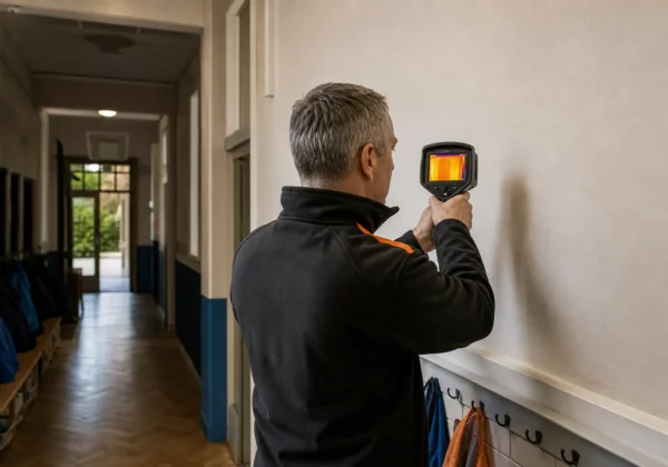
A thermal camera can show a cold bridge, but only when the survey conditions are right. Scan on a mild day and you may record colour changes rather than useful evidence.
Use this five-step method to plan the scope, prepare the building, capture images, test likely causes and turn the results into a repair plan. The same process can support heat loss surveys, retrofit work, roof investment and power purchase agreement reviews.
Step 1: Define the Cold Bridging Inspection Scope
Start by stating what the cold bridging thermal imaging survey must prove. A thermal image measures surface temperature. It does not see through a wall or measure heat flow on its own.
Write a short brief before anyone visits the site. Include the buildings, elevations, roof areas and rooms to inspect. Add the reason for the survey, such as reported mould, failed cavity insulation, retrofit checks or a planned energy project.
For a public estate, split the work into useful zones. A school may need classroom walls, roof edges and window junctions. An NHS estate may need plant-room interfaces, ward façades and areas with repeated condensation reports. A commercial investor may need a measured roof plan before assessing a power purchase agreement.
Set out the information needed at handover:
- Annotated thermal and visible-light images.
- Room or elevation references.
- Recorded indoor and outdoor conditions.
- Temperature differences at suspect areas.
- A roof plan or 3D model for large sites.
- CAD-ready dimensions where a roof may support a future energy project.
Ask for drawings, past repair records and retrofit details. Mark likely risk points before the survey. These include wall-to-floor junctions, parapets, slab edges, window reveals, balconies and service penetrations.
Use a recognised method where the findings may support a warranty claim or funding decision. Published thermal imaging guidance can help with survey planning and reporting. A full report should state its limits rather than present every colour shift as a defect.
Visual Perspectives Limited can combine thermal data with aerial images, photogrammetry and measured roof information. That gives investors a clearer view of roof condition before they assess a PPA, lease arrangement or retrofit option. By now, you should have a defined survey boundary and a list of decisions the evidence must support.
Step 2: Prepare the Building and Check Survey Conditions
Good cold bridging thermal imaging starts before the camera is switched on. The building needs a stable heat pattern, and the survey team must record any factor that could distort it.
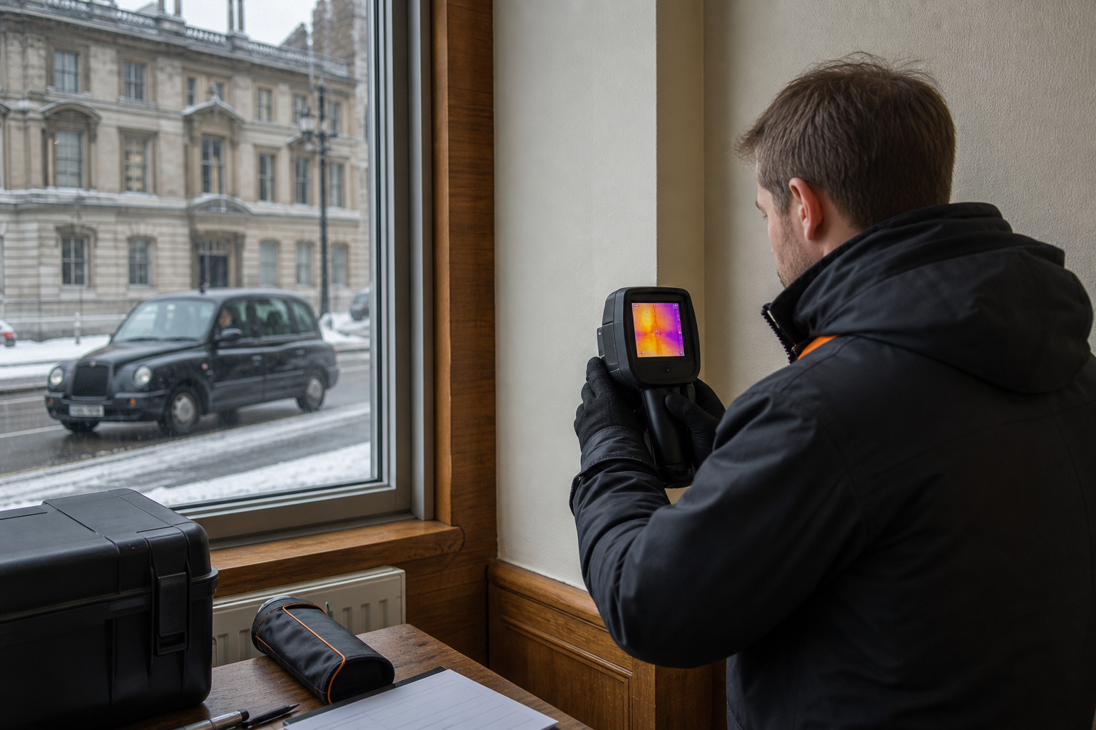
Plan the inspection during the heating season where possible. A useful working threshold is at least 10°C between inside and outside. A larger temperature difference can provide clearer evidence when conditions allow it.
Heat the building to its normal set point for at least 24 hours. Keep doors and windows in their usual closed state before the survey. Ask the facilities team to log unusual events, such as a boiler outage, open loading doors or a room left unheated.
Check the weather shortly before the visit. Avoid rain on the inspected surface. Avoid strong sun on façades because solar gain can make a wall appear warm after the defect has cooled. Night work or a uniformly overcast period often gives a steadier result.
Record:
- Indoor and outdoor air temperature.
- Relative humidity and dew point.
- Wind and recent weather.
- Heating, cooling and ventilation status.
- Surface condition and any wet areas.
- The time of each image batch.
Clear furniture away from internal walls where possible. Open access panels only when the survey brief allows it. Do not move items in a way that changes the building’s heat pattern just before imaging.
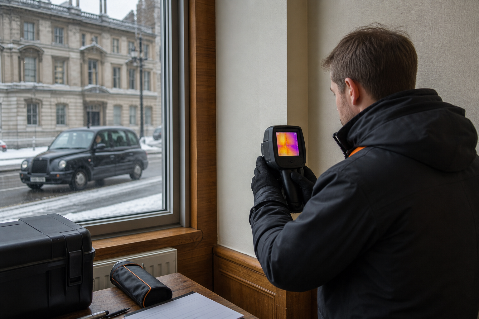
Material emissivity also matters. Painted plaster and brick usually behave differently from metal cladding, glass or polished fittings. Set the camera for the surface, control reflections and note the settings in the report.
If the conditions fall short, do not hide that fact. State the limitation and decide whether to postpone, use the images as a screening survey or add another test. A short delay is cheaper than a retrofit decision based on a false cold bridge.
Visual Perspectives Limited records survey conditions as part of its building defect thermography work. That helps a project team understand what the image proves, and what still needs a site check. You’ll be in good hands when the evidence starts with a clear audit trail.
Step 3: Capture Thermal Images Systematically
Cold bridging thermal imaging works best as a measured sweep, not a hunt for the most dramatic colour. Follow the same route each time so you can compare rooms, elevations and later surveys.
Begin with a visible-light walkaround. Note cracks, stains, damaged seals, vents and recent repairs. Then scan the building in a fixed order. Work clockwise around each floor, or follow an elevation grid. Mark each image with a building reference and location.
For internal work, aim the camera at the inner surface of the envelope. Check corners, reveals, skirting lines, wall-to-ceiling joints and service penetrations. Keep the camera steady. Use a consistent distance where the room allows it.
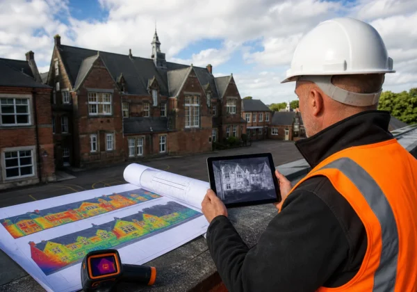
For a roof or façade, a drone can cover areas that would take much longer from access equipment. Capture overlapping RGB and thermal images. Keep the flight plan safe and consistent. The visible image helps identify whether a thermal anomaly sits beside a parapet, rooflight, plant item or drainage outlet.
Photogrammetry adds scale and position. Overlapping photographs can produce an orthomosaic or 3D model. Align the thermal layer to that model, then place each anomaly against a roof detail. This is useful when an investor needs a CAD-ready measured roof specification before reviewing PPA terms.
Save the original radiometric files when the camera supports them. A colour image alone may not preserve the data needed for later review. Capture a wider context image, then a closer view of the anomaly. Take a matching visible-light photograph from the same direction.
Do not trust the colour palette by itself. Change the viewing angle to check for reflections. A shiny panel can reflect the sky or a nearby heat source. Move side to side where safe, and compare the suspect surface with a similar surface nearby.
A thermal camera records infrared radiation and converts it into a surface temperature map. Camera setup, surface properties and viewing conditions affect the result.
For large estates, a drone survey can reduce the need for roof access. Visual Perspectives Limited combines aerial thermal imaging with high-resolution mapping, so a facilities team can locate an anomaly without relying on a vague roof description. A systematic image set is the milestone here, not a folder of unlabelled pictures.
Step 4: Interpret Cold Bridge Patterns and Test Alternatives
Interpreting cold bridging thermal imaging means reading patterns in context. A blue patch is a prompt for investigation, not a diagnosis.
Start with the building drawings and the visible-light image. Compare the suspect area with a nearby section built from the same material. Look for repeated lines at slab edges, columns, wall junctions or fixings. These patterns may indicate a thermal bridge through the structure.
Missing or compressed insulation often creates a broad patch or repeated stripe. A gap around a window may produce a narrow, irregular line. Air leakage can create a finger-like cool mark that follows a joint or opening. Moisture may cool a surface through evaporation, but its pattern can look different from a straight construction line.
Test each alternative before recommending work:
- Check moisture with a suitable moisture meter.
- Compare the area with a dry reference surface.
- Review heating and ventilation sources nearby.
- Change the camera angle to test reflection.
- Check whether the sun recently struck the surface.
- Compare the image with as-built details.
A blower-door test can help when air leakage is suspected. The pressure change makes incoming air easier to trace with thermal imaging. Without that pressure difference, a cold line near a door may be an insulation fault, a draught or simply a surface effect.
Use a line profile or spot measurement where the data supports it. Record the suspect temperature, the reference temperature and the measured difference. Avoid invented precision. If focus, distance or emissivity is poor, label the image for screening only and arrange a better survey.
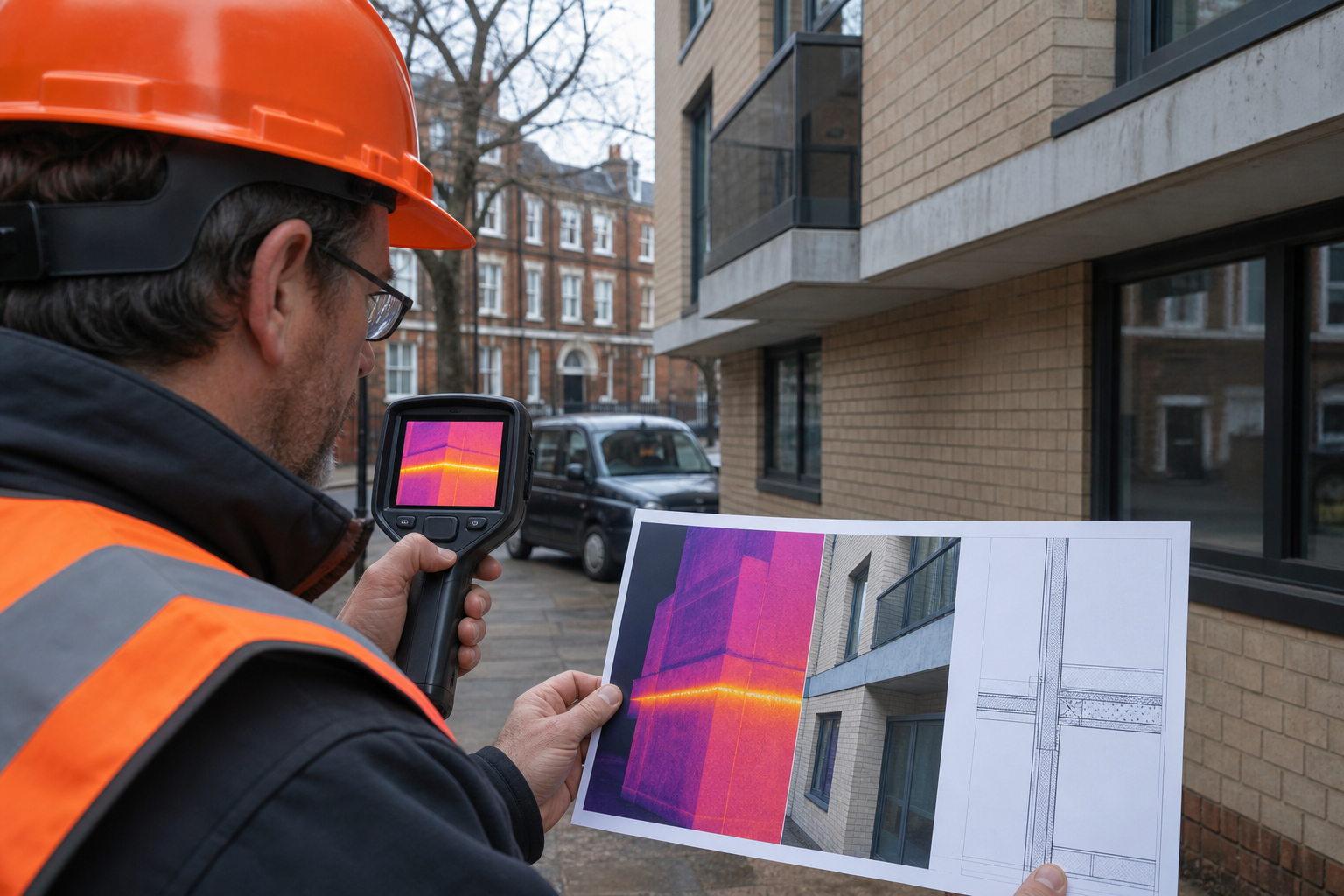
Normal corners can show colour changes because heat moves differently at a junction. A metal flashing can also create a strong line without proving missing insulation. The camera shows what the naked eye can’t see, but the surveyor still needs building physics and site checks to explain it.
For a public-sector portfolio, rank findings by risk and action. A cold bridge beside persistent mould needs a different response from a mild line at a structural junction with no moisture signs. Visual Perspectives Limited can pair thermal evidence with 3D mapping and roof condition records, helping the asset team see which findings need opening-up or repair.
Only classify an anomaly as a confirmed defect when the supporting evidence agrees. Otherwise, call it a suspected defect and state the next test.
Step 5: Turn Findings into a Defensible Repair and Retrofit Plan
The final stage of cold bridge imaging is to turn each finding into a decision. A good report tells the maintenance team where to act, why it matters and what evidence supports the recommendation.
Give every issue a unique reference. Show the thermal image beside the visible-light image. Add the floor, elevation or roof grid position. Include the recorded conditions and any measurement limits.
Group the findings by likely cause:
- Insulation gaps or discontinuity.
- Structural thermal bridges.
- Air leakage at joints and openings.
- Moisture-related cooling.
- Roof or façade defects that need a separate check.
Then set the next action. A suspected cavity insulation failure may need borescope work or a targeted opening-up survey. An air leakage pattern may need pressure testing. A roof anomaly may need a close visual inspection, moisture assessment or repair quote.
For retrofit, use the findings to improve the sequence of work. Repair water ingress before adding insulation. Resolve air paths before covering a junction. Review external wall insulation details around reveals, plinths and roof edges. PAS 2035 projects need a risk-led plan, not a thermal image attached to a generic specification.
For investors assessing a PPA, combine the thermal findings with roof measurements. A CAD-ready specification should state usable roof zones, obstructions, access points, edge conditions and areas that need repair. Photogrammetry can give the project team a measured base, while thermal imaging shows where roof condition or heat patterns need closer attention.
Do not treat a thermal survey as a structural report. It can guide inspection and reduce blind access work, but it cannot confirm every membrane, fixing or hidden substrate defect. State those boundaries clearly.
After repairs, repeat the survey under similar conditions where possible. Compare the same locations rather than relying on a new colour scale.
Visual Perspectives Limited provides independent thermal imaging, drone inspection and photogrammetry across the UK. For an estate manager, the useful outcome is a ranked work plan. For an investor, it is a clearer view of roof condition before money is committed. You’ll be in good hands when every recommendation links back to measured evidence.
FAQ
What is cold bridging thermal imaging?
Cold bridging thermal imaging uses an infrared camera to map surface temperature differences at building junctions. The pattern can point to missing insulation, structural bridges, air leakage or moisture. It does not or must compare the image with site conditions, drawings and other checks before naming the cause.
What temperature difference is needed for thermal imaging?
A difference of at least 10°C between inside and outside is a useful working threshold. The greater the stable difference, the clearer the contrast. Record the actual temperatures, because a survey taken in weak conditions may only provide indicative evidence.
Can a drone find cold bridges on a commercial roof?
A drone can help locate unusual thermal patterns across a large roof or façade, subject to safe flight conditions and suitable image resolution. It cannot replace close inspection where the cause is unclear. Pairing thermal images with RGB photographs and photogrammetry gives investors a measured roof view for PPA planning.
Can thermal imaging prove damp?
Thermal imaging can locate cool areas that may relate to moisture, but it cannot prove damp by itself. Evaporation can cool a wet surface, while air leakage and missing insulation can produce similar patterns. Confirm the finding with moisture readings, visible evidence and a check of nearby services or roof details.
Is thermal imaging useful for retrofit planning?
Thermal imaging is useful for finding weak points before retrofit work covers them. It can help target reveals, parapets, slab edges and insulation gaps. Use the results with a proper building assessment and the PAS 2035 process. Do not specify insulation from a colour image alone.
Conclusion
Plan cold bridge surveys around stable conditions, recorded settings and follow-up checks. For schools, hospitals, council buildings and investment portfolios, an independent survey can link thermal evidence with roof measurements and photogrammetry. Review Visual Perspectives Limited’s thermal imaging resource guide for buildings, then request a scoped inspection if your next PPA, retrofit or maintenance decision needs measured evidence.