A solar array can look fine while a loose connector or weak cell quietly cuts its output. A proper solar panel health check starts with safe observation, then moves to measured tests and thermal evidence. In 2026, UK inspection services split between large drone surveys and smaller handheld tools, so you need to check both the method and the data behind it.
Step 1: Record the System Baseline and Inspect the Panels
The first part of a solar panel health check is a safe record of the system as it stands today. Before touching anything, note the inspection date, weather, recent generation and any active inverter warnings.
Use the system’s generation records or inverter display to record daily output. If you have past records, compare the same month or similar clear-sky days. A single cloudy day tells you little. A steady fall across several clear days deserves attention.
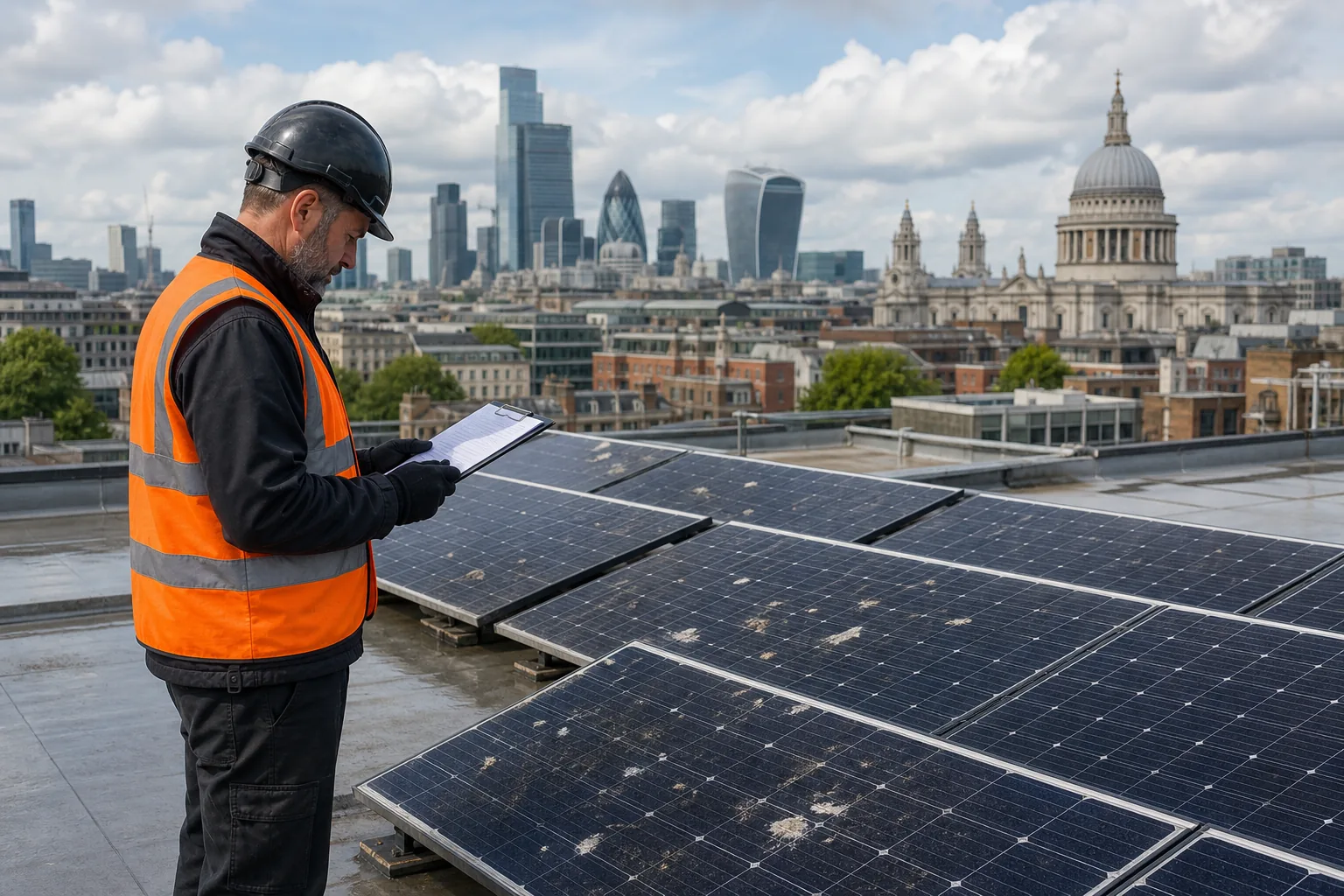
From ground level, inspect the array visually where needed. Look for cracked glass, dark cell marks, heavy bird fouling, leaf build-up and new shade from trees or nearby construction. Check for lifted panel edges or signs that the mounting system has moved.
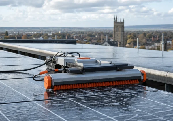
Cleaning needs care. Loose dust may wash away in rain, but dried bird fouling or sticky debris may remain. Never scrub a hot panel or climb onto a commercial roof without the right training, access plan and fall protection.
Record each concern against a panel number or roof zone. Take a wide image first, then a closer image. This gives the installer or surveyor enough context to find the same defect later. Our guide to finding and fixing solar panel problems follows this same evidence trail.
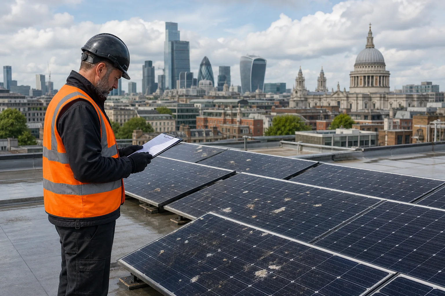
Visual inspection cannot prove that every cell is working. It can, however, explain some output changes before you arrange electrical testing. Shading deserves special care. A new building, plant room or tree can shade a row that was clear when the system was installed.
Photovoltaic systems convert light into electrical power, so shade, dirt and physical damage can affect generation even when the inverter shows no fault.
Step 2: Check Generation, the Inverter and Electrical Output
This stage checks whether the solar panel health check matches the numbers shown by the system. Start with the inverter because it gives a quick view of DC input, AC output, daily energy and lifetime generation.
Read the inverter display for fault codes, warning lights and unusual values. A persistent red or amber warning needs a qualified technician. Check the monitoring connection too. If the inverter has stopped sending data, the panels may still be producing power, but you have lost your view of performance.
For a small standalone panel, a trained person can compare open-circuit voltage with the value on the panel label. Set a suitable meter to DC voltage first. Place the probes on the matching positive and negative connectors, without touching exposed metal or allowing the probes to bridge the terminals.
Current testing carries more risk. The meter must be rated above the panel’s short-circuit current. Move the lead to the correct current socket before testing. Covering the panel until the leads are in place can reduce the initial spark, but it doesn’t make a live DC test safe for an untrained person.
For a panel connected to a system, a clamp meter may measure current without opening the circuit. A DC power meter can show watts when fitted in line with the panel and charge controller. Compare the result with the label’s rated values, while allowing for cloud, angle, season, temperature and a nearly full battery.
Do not treat a lower reading as proof of a failed panel. Thin cloud can reduce current. A charge controller can also limit power when the battery is nearly full. Test one panel or string at a time where the system design allows it, then compare matching strings under similar conditions.
A professional inspection may include string voltage, current, insulation resistance and inverter-side checks. Visual Perspectives Limited combines these records with thermal and aerial evidence for commercial and public roof PV systems. That matters when an asset manager needs to separate a module fault from a wiring fault.
By now you should have a generation record, inverter status and a clear reason for any electrical test.
Step 3: Examine Wiring, Isolation, Earthing and Mounting Safety
A complete solar panel health check must include the equipment around the panels. Many faults sit in connectors, cables, isolators or mounting points rather than in the module face.
From a safe position, look for hanging cables, damaged insulation, rodent marks, loose cable ties and connectors that appear partly open. Check the route below the panels where it can be seen. Cables should not rub against sharp metal or rest in standing water.
Inspect the AC and DC isolation equipment for damage, heat marks or a changed switch position. Do not open live distribution boxes. An indicator on protective equipment can suggest normal status, but it does not replace electrical testing.
Earthing needs a competent person and suitable test equipment. A visual check can find a detached earth conductor or corrosion at an accessible bonding point. Continuity and insulation resistance tests confirm whether the protective system works as intended.
Mounting checks are just as important on public buildings. Look for loose clamps, corrosion, shifted ballast and failed roof seals. On a flat roof, inspect the membrane near supports, cable routes and penetrations. Water entry can damage the building even when the PV system still generates power.
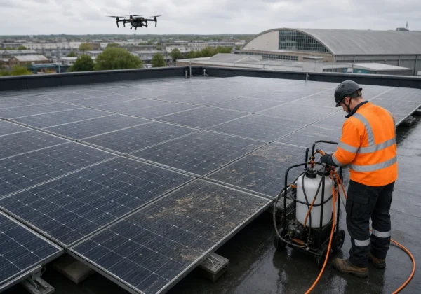
Drone access helps when roof access would expose staff to avoidable risk. Visual Perspectives Limited provides managed drone surveys across the UK, with high-resolution mapping that links roof defects to the PV layout. The result is quickly, precise, and detailed evidence without asking someone to walk across every roof area.
Use the commercial solar panel survey guidance when you need to set the inspection scope before appointing a survey team.
Stop the DIY process at this point if you find burnt wiring, exposed conductors, water inside an enclosure or an unstable roof fitting. You’ll be in good hands when a qualified electrical contractor takes over.
Step 4: Use Thermal Imaging to Find Hidden Defects
Thermal imaging shows what the naked eye can’t see. It maps heat across operating modules, strings and balance-of-system components so you can locate abnormal patterns.
A healthy module usually has a fairly even thermal pattern. A bright local spot may point to a cracked cell, increased resistance or physical damage. A warmer section across roughly one part of a panel may indicate bypass-diode activation. Broad heating across a string needs electrical follow-up rather than a quick panel swap.
Thermal imaging can also identify heat at junction boxes, connectors, combiner boxes, disconnects and inverters. Skipping these parts leaves a gap in the inspection because a loose connection may heat up before it fails.
Good conditions matter. Scan while the array is producing power, with strong and steady sunlight. Recent rain, passing cloud, glare and high wind can weaken or distort the result. Record irradiance, wind, ambient temperature, camera settings and the inspection time.
IEC 62446-3 gives a framework for PV thermographic inspection. Ask the provider how its camera, flight height and lens support the inspection.
The market is surprisingly quiet about these details. Just 10% disclosed thermal resolution. Only 38% stated IEC 62446 compliance. Technology alone doesn’t prove that the survey will support a warranty or insurance decision.
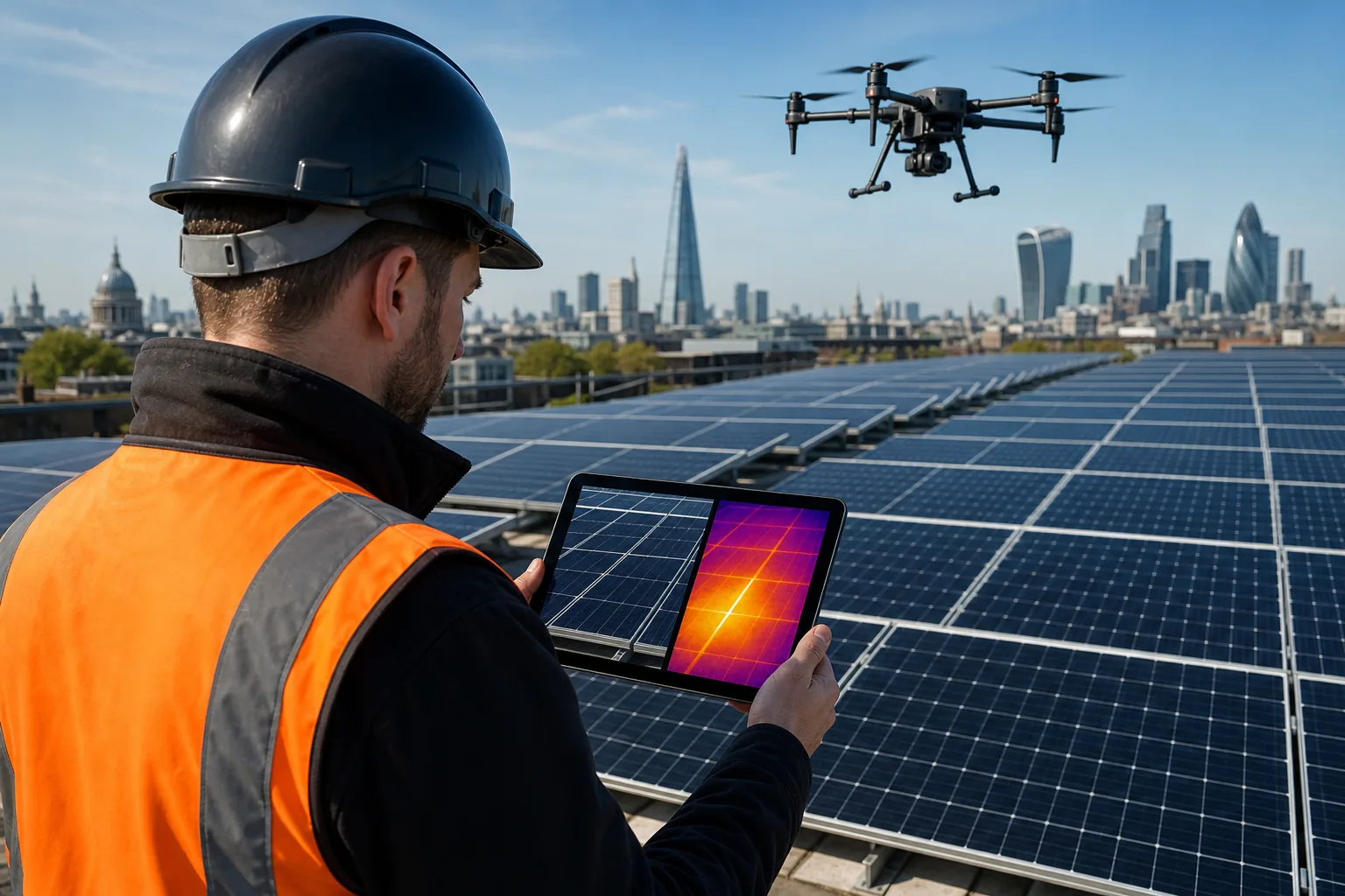
Visual Perspectives Limited provides IEC 62446-compliant thermographic reporting for commercial and public roof PV installations. Its stated spatial resolution is 4 cm per pixel. That type of detail helps map a finding back to a panel instead of leaving a maintenance team with a vague warm patch.
Thermal evidence still needs context. Compare the suspect area with nearby modules under the same load. Match the thermal image to an RGB image and the panel or string reference. Then confirm the likely cause with electrical testing where needed.
A thermal anomaly is a diagnosis lead, not always a final diagnosis. Re-scan after repair under similar conditions. If the heat pattern remains, the first repair may not have addressed the cause.
For a wider view of the workflow, see our guide to reading a solar panel inspection report. You’ll be in good hands when the report links each image to a location and a clear next action.
Step 5: Assess Batteries, Monitoring Data and the Inspection Report
The final stage turns a solar panel health check into a maintenance decision. If the system has batteries, assess them separately from the PV array.
For battery systems, follow the battery maker’s instructions for checking condition. Only use any consumables where the battery maker permits it. A multimeter can compare the voltage of individual units. A battery tester may also show state of charge and electrolyte condition.
Do not open battery enclosures or handle electrolyte as a casual DIY task. Battery chemistry varies, and a qualified installer should carry out tests that require access to live terminals or internal cells.
Review monitoring data over time rather than relying on one reading. Look for a sudden fall in daily generation, repeated differences between strings or missing data from the inverter. Check whether the change matches weather, shade, soiling or a battery that has reached full charge.
A useful report should state the site, inspection date and system scope. It should also show environmental conditions, the method used and the areas that could not be inspected.
- Include a panel or string map.
- Match each defect with visual and thermal evidence.
- Record voltage, current or insulation results where taken.
- State the suspected cause and severity.
- Give each action an owner and target date.
- Keep warranty, repair and cleaning records together.
Ask whether the report follows IEC 62446-3 and whether the scope included electrical tests. A thermal-only survey can locate anomalies, but it may not prove the cause. That distinction matters during an insurer review, warranty claim or handover to an O&M team.
For large estates, repeat the same method so results remain comparable. Visual Perspectives Limited supports building owners, facilities teams and public sector estates with drone inspection, thermal imaging and mapped reporting. This gives you a record that can feed future roof work and decarbonisation planning.
Use a simple action order: address immediate electrical or fire risks first, then repair faults that reduce output, then plan cleaning and minor fabric work. Early evidence gives your team time to budget instead of reacting to a failed array.
Frequently Asked Questions
Can a multimeter be used to test solar panels?
You can test a small, isolated panel with a correctly rated multimeter, but live DC work can cause shock, burns or arcing. Read the panel’s voltage and current ratings first. Use DC settings and the correct meter sockets. For roof arrays, ask a qualified solar engineer to test strings, isolation resistance and protective systems.
What does thermal imaging find on solar panels?
Thermal imaging can find hot spots, failed cells, bypass-diode patterns, string anomalies and heat at connectors or junction boxes. These signs are often invisible during a visual solar panel health check. Thermal data needs steady sunlight and skilled interpretation because shade, glare, wind or dirt can create misleading patterns.
What should a solar inspection report include?
A useful report includes the inspection date, site details, method and weather conditions. It should map each defect to a panel, string or component. Include matched RGB and thermal images, relevant electrical readings, severity, likely cause and a recommended action. It should also state whether IEC 62446-3 formed part of the inspection scope.
When should I use a drone solar inspection?
Use a drone inspection when the array is large, difficult to access or installed on a busy commercial or public roof. A drone can capture consistent visual and thermal data while reducing the need for roof travel. It cannot remove the need for competent analysis, safe flight planning or electrical follow-up.
Conclusion
Start with a safe baseline, then confirm unusual readings with qualified electrical testing and thermal imaging. For a commercial or public building, appoint an independent inspection team that can map findings to the roof and PV system. Visual Perspectives Limited provides nationwide drone and thermographic surveys, so you can turn inspection evidence into a clear maintenance plan.