A solar array can look fine while a cracked cell, failed diode or hot connector quietly cuts output. Some losses are obvious, such as shade across a panel. Others need thermal imaging because they show what the naked eye can’t see. Work through these five steps before you approve repairs or make a warranty claim.
Step 1: Check the Solar PV System for Visible Warning Signs
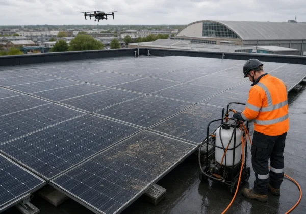
Start with a safe ground-level check. Visible clues can explain sudden output loss and help you decide whether a full Solar PV Inspection is needed.
Don’t climb onto a commercial roof or touch DC equipment unless you’re trained and authorised. First review the inverter display and monitoring data. Look for warning codes, a sudden drop in daily generation or a string that performs well below its usual level on a clear day.
Next, inspect the array from the ground. Use binoculars where needed. Look for:
- Cracked glass or visible cell lines.
- Heavy bird fouling, dust, sap or leaf build-up.
- New shade from plant growth, roof plant or nearby construction.
- Loose clamps, lifted edges or signs of movement.
- Damaged cable insulation or connectors.
- Water marks, staining or signs of roof damage near the mounting system.
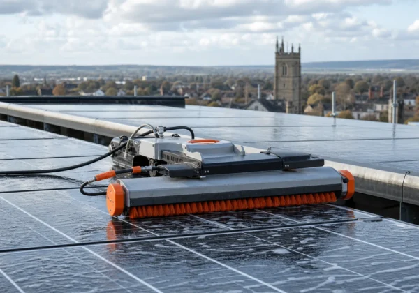
Shade deserves prompt attention. A single obstruction can affect the output of a panel string, even when the rest of the array appears clean. A visual check also helps you spot soiling, but it can’t confirm the condition of cells beneath the glass. Further reading.
Record the date, weather, inverter reading and exact location of each concern. Take wide photos first, then closer images. This gives an installer or surveyor enough context to find the same panel later.
For a planned maintenance cycle, use our guidance on solar panel maintenance for commercial roofs to set a sensible inspection record. You’ll be in good hands when each finding has a location and a photo.
Step 2: Use Thermal Imaging to Locate Hot Spots and Electrical Faults
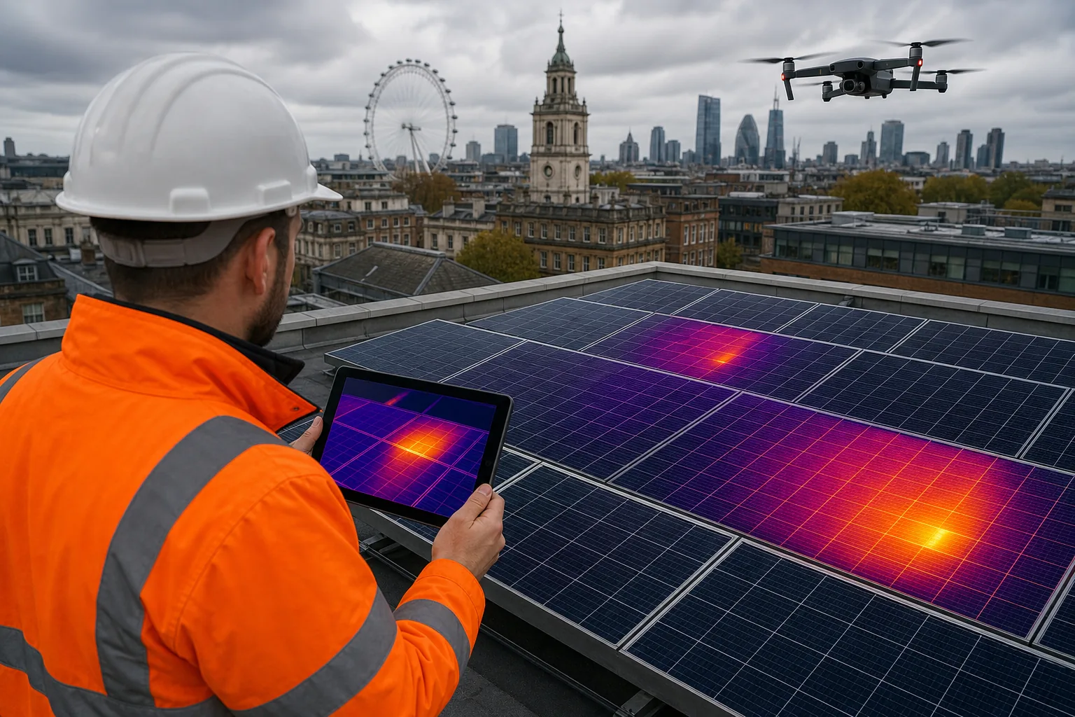
Thermal imaging is the key test for many solar panel problems because it maps heat across the operating array. A healthy panel tends to show a fairly even pattern. A fault can appear as a sharp hot spot or a broad warm section.
Cracked cells can create local heating. Corroded MC4 connectors and loose terminals can also heat at the point of resistance. A bypass diode failure often affects a whole section of the module, rather than one small cell. The pattern matters as much as the temperature.
Hot spots may account for only 0.5% to 3% of total generation loss, yet they can worsen if ignored. A failed bypass diode can reduce module open-circuit voltage by roughly 33%, based on the supplied technical research. Treat those figures as indicators, not a repair quote. Site conditions and system design still need review.
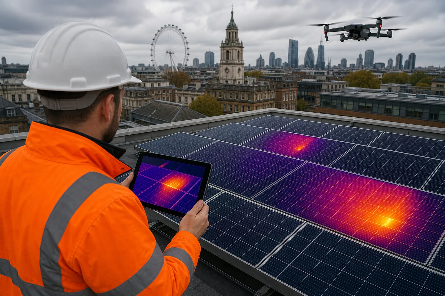
Good data depends on good conditions. Scan while the system is producing power, with steady sunlight and no recent rain. Passing cloud can flatten temperature differences. Glare can also create false patterns on glass.
A competent thermographer records the array layout, panel position, string reference and component type. The inspection should include more than the panel faces. Combiner boxes, junction boxes, disconnects and inverters may show heat linked to loose wiring or failing components.
IEC TS 62446-3 sets requirements for infrared inspection of PV systems. One detail is image resolution. Each PV cell needs enough pixels to make a small fault visible. Camera distance and lens choice therefore matter. A distant low-resolution image may look impressive but fail to support a sound diagnosis.
Thermal imaging shows an anomaly, not always its cause. Re-scan a suspect area under stable conditions. Then compare it with nearby cells under the same load. Infrared thermography uses cameras that measure emitted heat rather than visible colour; learn more.
Visual Perspectives Limited provides drone-based thermographic inspections with high-resolution data and reports aligned with IEC 62446 requirements. We work quickly, precise, and detailed, so small faults have a clear place in the maintenance plan. You’ll be in good hands.
Step 3: Trace the Fault Through Strings, Connectors and the Inverter
Once thermal imaging finds an abnormal area, trace the fault through the system. Solar panel problems often sit in the wiring path rather than in the module itself.
Start at the affected panel position. Match the thermal image with the array plan. Then identify the string, combiner input and inverter MPPT, which is the inverter channel that tracks the panel voltage.
Do not disconnect live DC connectors as a quick test. A qualified solar engineer should carry out electrical checks under the site’s safe system of work. Useful checks may include string voltage, current, insulation resistance and connector condition. The exact test plan depends on the system design and the engineer’s competence.
Use the thermal pattern to guide that work:
A dead string has no useful heat signature at the combiner box because it isn’t delivering power. A hot string shows the opposite pattern. Neither finding should be judged from colour alone. Confirm it with measured values.
Also inspect the inverter log. Repeated insulation, arc or ground-fault warnings can point to a wider issue. A clean inverter screen doesn’t prove that every module is healthy, so don’t stop there.
For related survey information, see this guide. A wider view helps when a roof project involves both PV defects and moisture concerns.
Finish this step with a fault map. Give each issue a panel number, string reference, image reference and proposed test. It turns a vague complaint into a controlled handoff between the surveyor and installer.
Step 4: Combine Drone Roof Inspection Findings with Building Condition Evidence
A drone roof survey puts solar panel problems into the wider roof condition record. That matters because PV work can hide membranes, drains and edge details from normal view.
Ask the survey team to inspect the roof around the array. Look for ponding, damaged membrane, failed flashing, blocked drainage and signs of water entry. On a flat roof, thermal data may also point to trapped moisture, although moisture findings need suitable weather and specialist interpretation.
Compare the roof evidence with the PV layout. A panel row over a wet or damaged area may need a different repair sequence from an isolated module fault. Removing panels before the roof is repaired can add cost and delay. Leaving a roof defect below a working array can cause a second failure later.
Drone access reduces the need for repeated roof access, but it doesn’t remove the need for a competent inspection plan. Set a safe launch area. Check airspace and site controls. A CAA-authorised operator should manage the flight and protect people below.
Visual Perspectives Limited combines high-resolution aerial imagery with thermal inspection and 3D mapping. We can help asset managers compare roof condition with PV locations across a school estate, NHS estate or wider public sector portfolio. The result is quickly, precise, and detailed evidence for planned investment.
Keep the roof report and PV report joined by location. A defect that appears minor in one report may change priority when both records point to the same roof zone.
That is the decision rule: repair the building fabric first when it threatens the system, the roof warranty or safe access.
Step 5: Prioritise Repairs, Verify the Work and Record the Evidence
Turn the findings into an action list. A report only helps when someone can decide what happens next.
Rank each defect by safety risk, energy impact, likelihood of worsening and warranty deadline. A hot connector or severe diode fault should usually move ahead of routine cleaning. A small area of soiling may wait for the next planned visit if generation remains stable.
Give every action an owner and due date. State whether the next action is cleaning, electrical testing, module replacement, connector replacement, roof repair or further investigation. Don’t tell an installer to “fix the hot spot” without giving its panel and string reference.
After work is complete, verify it. Ask for the replacement details where relevant. Record the final electrical reading. Re-scan the repaired area under comparable operating conditions. A thermal signature that remains after repair suggests the first action did not address the cause.
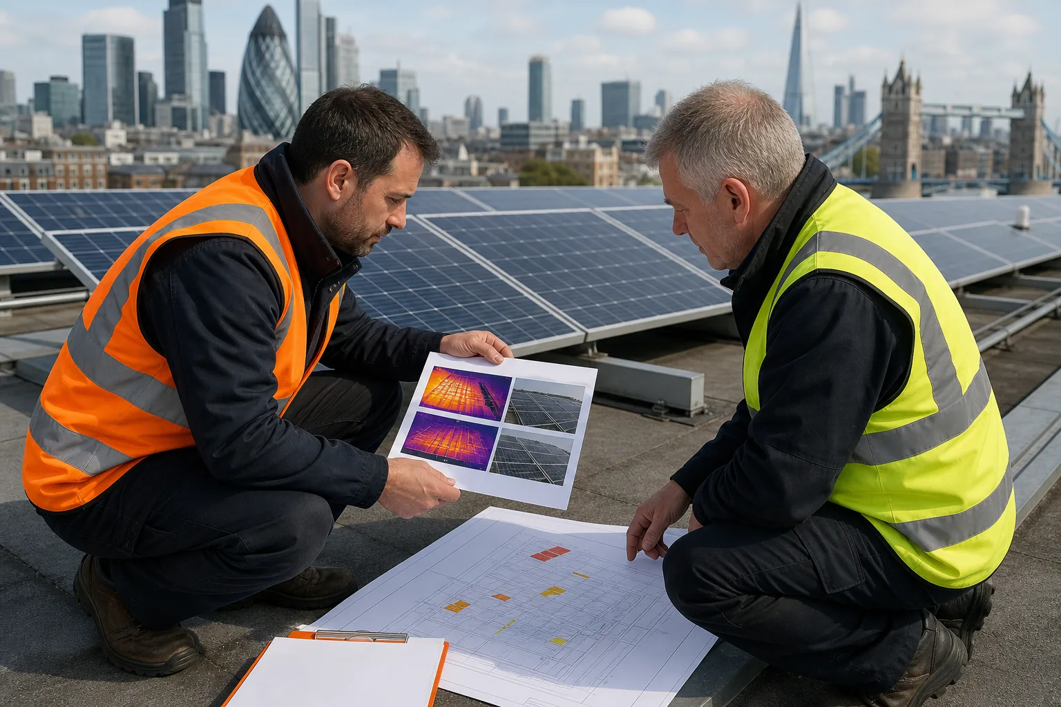
Keep a single evidence pack for the site. Include:
- Array plan with panel and string references.
- Original RGB and thermal images.
- Inverter readings and electrical test results.
- Roof condition findings.
- Repair instructions, invoices and warranty documents.
- Post-repair images and close-out notes.
Digital records are easier to compare across a portfolio. They also help when a facilities manager changes, an insurer asks for evidence or a funding project needs a clear condition baseline.
Visual Perspectives Limited provides independent inspection evidence for building owners, surveyors, installers and asset managers across the UK. We remain separate from the installer, which helps keep the diagnosis impartial. Our reports support a defensible repair decision without asking you to rely on guesswork.
For a formal warranty or handover review, our Solar Panel Thermal Imaging Inspections service can combine roof and PV findings. You’ll be in good hands when the final report shows what was found, what changed and what still needs attention.
FAQ: Solar Panel Problems
What are the most common solar panel problems?
The most common solar panel problems include shading, soiling, cracked cells, hot connectors, failed bypass diodes and dead strings. Some are visible from the ground. Others appear only when the system is operating and a thermal camera maps abnormal heat.
Can thermal imaging find faults that look normal?
Yes, thermal imaging can find faults that look normal during a visual check. Cracked cells, loose terminals and corroded connectors can produce local heat without obvious surface damage. The scan still needs suitable sunlight, correct camera resolution and a trained review.
How do I know if a solar panel has a hot spot?
A thermal image can show whether a solar panel has a hot spot. The surveyor compares the warm area with nearby cells under similar load. A full visual check should follow, because dirt, shade or reflection can create a misleading pattern.
Are solar panel problems dangerous?
Some solar panel problems can create a safety risk, especially faults involving hot connectors, damaged cables or electrical resistance. Don’t touch or disconnect equipment yourself. Isolate the system through a qualified engineer and arrange thermal or electrical testing when the evidence points to a fault.
How often should commercial solar panels be inspected?
Commercial solar panels need a planned inspection schedule based on system age, roof conditions and operating risk. A thermal baseline after commissioning can support later comparison. Sites with harsh exposure, repeated faults or high operational importance may need more frequent checks.
Conclusion
Start with a safe visual check, then use thermal imaging and qualified electrical testing to confirm the cause. For commercial roofs, an independent drone survey can link PV defects with roof condition and give your team a clear repair record. Visual Perspectives Limited provides nationwide inspection support, so the next step is to arrange a survey before a small fault becomes a larger maintenance problem.