Solar PV faults can hide behind a clean-looking panel. Safe solar panel testing combines site checks, visual inspection, electrical readings and thermal imaging, rather than relying on one meter reading. Follow the steps below for small systems, commercial roofs and formal inspection work.
Step 1: Define the Testing Scope and Prepare the Site
Start solar panel testing by deciding what you need to prove. A quick check on a single module is very different from a documented inspection of a commercial PV array.
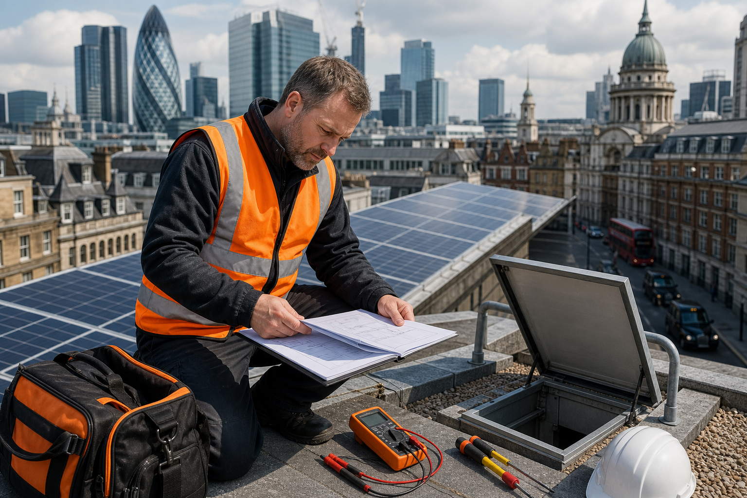
Write down the system details before you attend. Record the panel make and model, rated power, voltage and current. Note the inverter type, number of strings, array layout and any past fault reports. If available, obtain the commissioning record and the latest performance data.
Then define the test goal. You may need to check one suspected faulty panel. You may need string-level evidence for an insurer, warranty claim or planned repair. A full commercial survey may need visual inspection, electrical testing, thermal imaging and a report aligned with IEC 62446-3.
Check the roof before anyone climbs onto it. Look at roof age, access points, fragile areas, skylights, weather and nearby trees. Shade can change readings, while a wet or unsafe roof can stop the test altogether. Roof age, slope and tree cover can affect whether a site is suitable for solar.
Make a site risk plan. Isolate equipment only when the test method requires it, and follow the system owner’s switching procedure. Remember that PV modules produce DC power whenever light reaches them. Covering a module reduces output, but it doesn’t make damaged wiring safe.
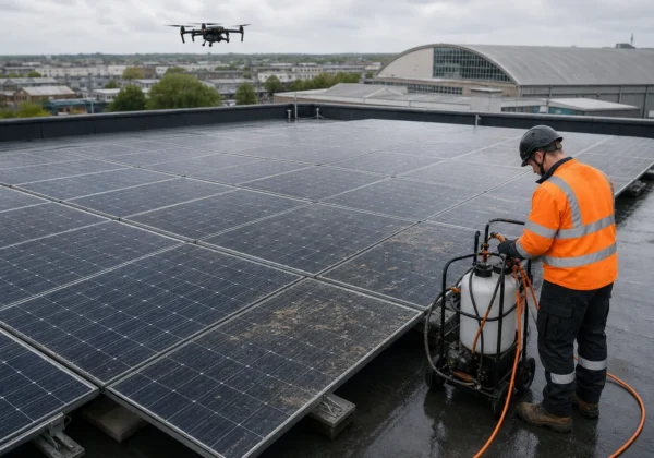
For large roofs, we use a drone roof survey to reduce work at height. Visual Perspectives Limited is independent of installers, so we can inspect the roof and array without marking our own work. Our surveys are quickly, precise, and detailed, while showing what the naked eye can’t see.
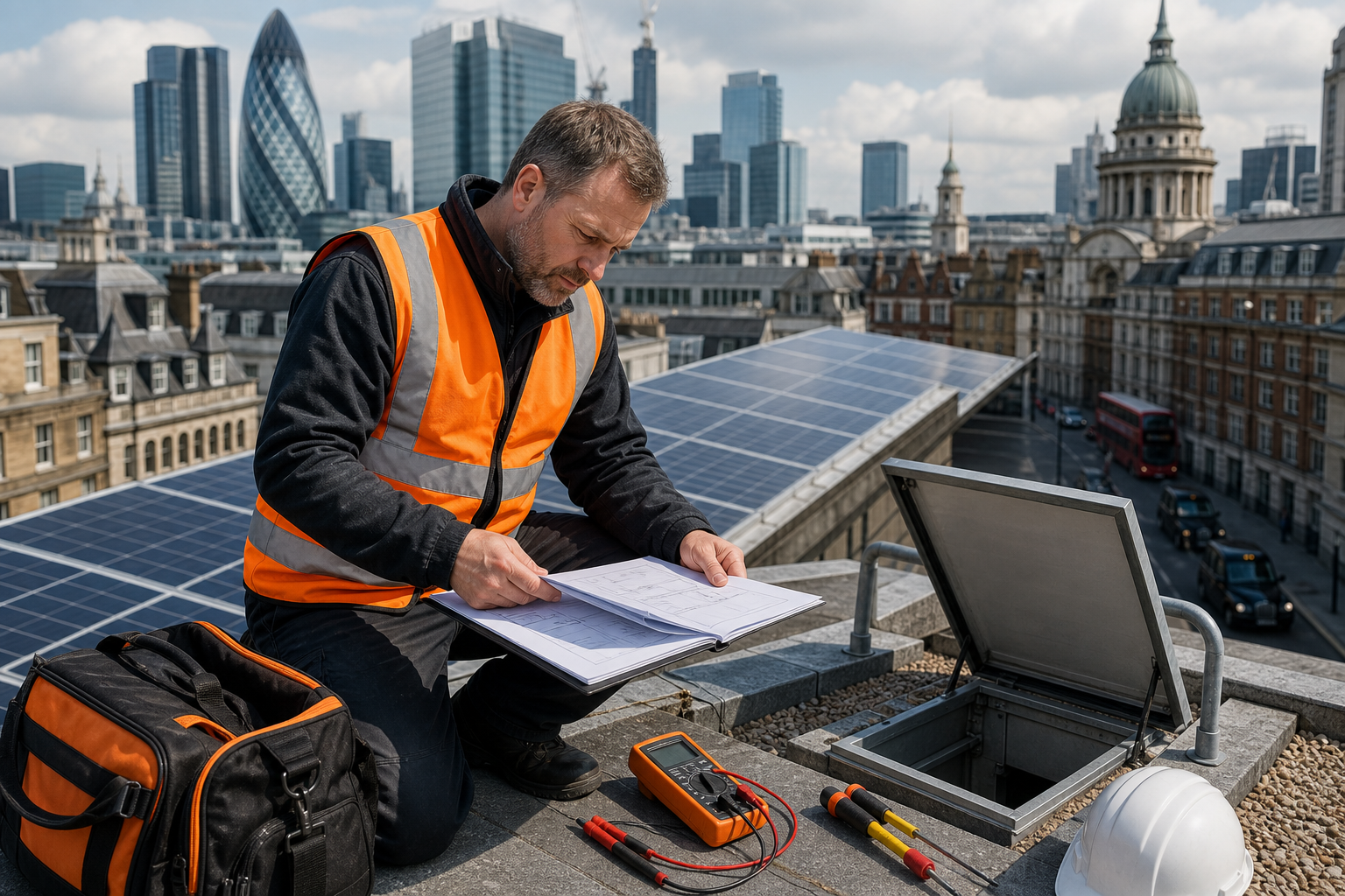
By now you should have a test plan, a safe access method and the documents needed to judge the readings.
Step 2: Complete a Visual and Mechanical Inspection
Visual inspection is the first physical stage of solar panel testing. It can find damage that electrical readings alone may miss.
Inspect from a safe position before approaching the array. Look for cracked glass, damaged backsheets, delamination, discolouration and signs of water entry. Delamination means layers within the module are separating. It can allow moisture in and may worsen over time.
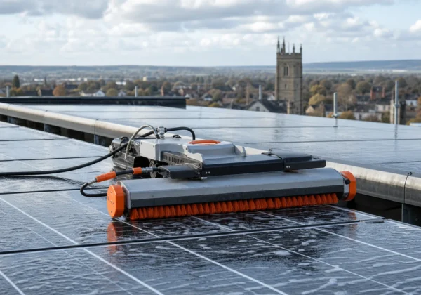
Check for heavy soiling, bird fouling, leaf cover and new shade. A small patch of shade can affect a cell group and may produce a misleadingly low output. Note the time and weather, because the same panel may read differently after the obstruction is removed.
Study the frame and mounting system. Look for lifted edges, loose clamps, corrosion and movement around fixings. Check that cables are supported and protected from sharp edges. A cable resting against a roof surface can suffer damage even when the panel itself looks sound.
Inspect connectors without pulling them apart. Look for poor alignment, heat marks, cracked housings and mismatched connector types. Do not handle a suspect connector while the circuit is live. A qualified person should isolate the circuit and confirm the safe state first.
Pay close attention to the junction box and cable entry points. Heat marks, brittle seals or staining need a closer check. The inverter display may show an earth fault or string fault, but its message does not identify the physical cause.
Take a clear image of each defect. Give every row, module or string a reference that matches the layout drawing. A useful inspection record lets a maintenance team find the same panel without guesswork.
Solar systems can work in many climates, but local conditions still affect performance. That is why shade, dirt and roof condition belong in the inspection record.
Do not tighten a clamp or clean a panel simply to make the defect disappear. Record its original state first. The evidence may be needed later for a warranty or insurance decision.
Visual Perspectives Limited can combine high-resolution aerial images with thermal data across commercial roofs, schools and public buildings. You will be in good hands when each finding has a location, image and clear next action.
Step 3: Carry Out Electrical Tests and Compare the Results
Electrical testing checks whether the PV system is producing the voltage and current its design suggests. It must be done by a competent person with equipment rated for the system’s DC voltage and fault level.
Start by confirming polarity. A reversed connection can damage equipment or produce a false fault. Check the meter leads, range and category rating before connecting anything. Never place a multimeter across a current setting directly on a voltage source. That can create a short circuit.
For a basic module check, measure open-circuit voltage, known as Voc, only when the test method and isolation procedure allow it. The module is disconnected from its load, and the reading is compared with the manufacturer’s rated value. A low Voc can point to shade, a wiring fault, cell damage or a module problem.
Current needs more care. A short-circuit current test, Isc, routes current through a suitable meter or test device. It should not be improvised with an ordinary meter. For an installed array, a clamp meter or current shunt may measure current without breaking the circuit, provided the instrument suits the DC system.
A load test gives a more useful picture of working output. Connect the panel to a suitable load or electronic load through the correct protective equipment. Increase the load in controlled steps and record voltage and current at each point. An IV-curve tracer automates this process and shows where maximum power differs from the expected curve.
Do not compare a field reading with a nameplate value without noting conditions. Cell temperature changes voltage. Irradiance changes current. Cloud edges, haze, reflection and partial shade can all affect the result.
Compare like with like. Test neighbouring strings under the same sky, then check the manufacturer’s data. A single low reading needs investigation, not an instant verdict.
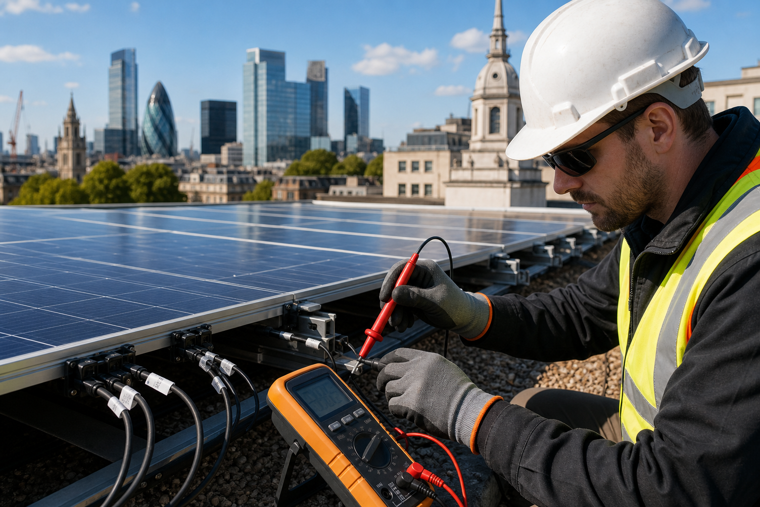
Our commercial solar panel inspection process combines electrical checks with thermal evidence. That matters because a meter can show that output is low, while thermal imaging may show which module or connection needs attention.
By now you should have repeatable readings tied to specific strings or modules. If the circuit cannot be made safe, stop and use a qualified solar PV tester.
Step 4: Use Solar Thermography to Locate Heat-Related Defects
Solar thermography adds a heat map to solar panel testing. It can reveal hot cells, failed bypass diodes, poor connections and uneven loading that a ground-level visual check may miss.
Plan the survey for useful operating conditions. The array needs enough sunlight to create a clear thermal difference. Strong reflection from glass can mislead the camera, while wind can cool a defect and reduce its visible contrast.
Use thermal imaging equipment and keep the camera angle as close to the recommended method as site conditions allow. Capture the whole array first. Then take closer images of each anomaly beside a normal panel for comparison.
A warm patch is a clue, not a diagnosis. A hotspot may come from cell damage, shading or a poor connection. Check the RGB image, panel reference and electrical reading before raising a repair order.
For a large commercial roof, drone thermography can cover the array quickly without sending staff across every row. It also links each thermal image to a roof position. That helps an FM team reach the right module on the first visit.
IEC 62446-3 is useful when the output needs to support an insurer, owner or warranty claim. It sets a common basis for outdoor infrared thermography of PV modules, so the report can state the conditions and method rather than showing unexplained coloured images.
Classify findings by risk. A severe local temperature rise near a junction box deserves faster action than a small area of soiling. But don’t use a colour scale alone. Tie the severity to the likely cause, electrical evidence and access risk.
Visual Perspectives Limited uses drone-based thermal imaging across UK commercial roofs and public estates. We provide quickly, precise, and detailed evidence of what the naked eye can’t see, without treating every warm pixel as a failure.
Step 5: Record Findings, Verify Faults and Produce an Action Plan
The final stage of solar panel testing turns readings into decisions. A report should help an asset manager decide what needs action first.
Give every issue a unique reference. Include the roof zone, row, module or string, date, time, weather and test conditions. Add the relevant visual image, thermal image and electrical reading. State when a result could not be confirmed.
Group faults by likely cause. A shaded module needs a different response from a failed bypass diode. A hot connector may need immediate isolation, while soiling may need a planned clean followed by a repeat check.
Verify important faults before recommending replacement. Repeat the reading under comparable conditions. Check the cable path and nearby modules. Review inverter logs where they are available. If the evidence still conflicts, arrange a closer inspection by a qualified PV engineer.
Build the action plan around risk and access. Mark safety-critical defects first. Then list faults that reduce generation or may spread. Add a suggested owner, target date and close-out evidence for each item.
For warranty work, keep the original files, not only screenshots in a PDF. A clear chain of evidence makes it easier to discuss the finding with an installer or insurer. Our solar panel warranty inspection guidance explains why roof condition and ongoing PV records belong together.
Visual Perspectives Limited can deliver an independent report for property owners, surveyors, facilities teams and solar installers. We work nationwide and can help you move from a fault map to a sensible maintenance plan. You will be in good hands.
FAQ
How do you test a solar panel with a multimeter?
You can measure voltage with a correctly rated multimeter, but only after checking the system method and safe isolation procedure. Set the meter for DC voltage, confirm polarity, then compare the open-circuit reading with the panel specification. Current tests need more care because an incorrect connection can short the circuit or damage the meter.
What should a healthy solar panel read?
A healthy panel should produce readings close to its rated values under comparable test conditions. The exact result changes with sunlight, cell temperature, shade and load. Compare neighbouring modules or strings, then check the manufacturer’s data. One low value doesn’t prove a failed panel, so confirm the wiring and conditions before replacing it.
Can solar panels be tested under load?
Yes, solar panels can be tested under load with suitable load equipment, electronic load or IV-curve tracer. Record voltage and current as the load changes. This shows working output more clearly than Voc alone. Use equipment designed for the circuit, and keep a qualified person in charge of live DC testing.
What does thermal imaging find on solar panels?
Thermal imaging can find abnormal heat linked to cell damage, shading, poor connections or bypass diode faults. It doesn’t identify the cause on its own. Check the thermal image against a normal panel, visual evidence and electrical readings. For formal work, record the weather and method so another person can review the result.
How often should commercial solar panels be tested?
Commercial PV systems should follow the owner’s maintenance plan, warranty terms and insurance requirements. Test after severe weather or when generation changes without a clear reason. A planned inspection can combine visual, electrical and thermal checks. The right interval depends on the array, roof access, environment and consequences of failure.
Conclusion
Carry out solar panel testing as a controlled investigation, not a quick meter check. For commercial roofs or public buildings, commission an independent survey that joins visual inspection, electrical evidence and IEC 62446-3 solar thermography. Visual Perspectives Limited provides nationwide drone and thermal inspection services, so your next action can be a documented site review with findings your maintenance team can use.