Running a solar PV array without proper testing is a gamble. A missed hotspot or loose fix can cost money, time and even safety. Below is a usable, step‑by‑step guide that lets you run a full solar PV testing programme from start to report.
Step 1: Define the Solar PV Testing Scope and Safety Controls
First, write down what you need to check. Are you confirming a new installation for warranty compliance? Or are you doing a periodic health check for a public‑sector estate? The scope decides which tests you run, how detailed the reporting must be, and which standards apply.
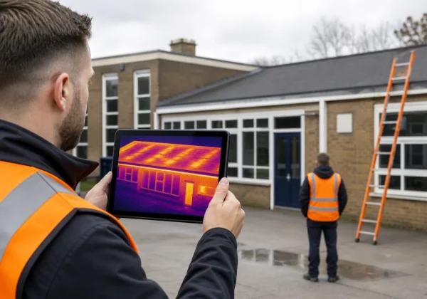
Next, lock in safety controls. All drone work in the UK must be covered by a CAA Category 2 authorisation and a minimum £5 million public liability policy , both of which Visual Perspectives Limited holds How to Carry out Solar Panel Testing Safely. On‑site staff need to wear hard hats, high‑visibility clothing and fall‑protection when accessing the roof. If you plan to work near live conductors, isolate the array and verify that grounding resistance is below 1 Ω before anyone steps onto the surface.
Finally, decide the documentation format. IEC 62446‑3 requires a written report that includes weather conditions, irradiance level and timestamps for every image. You can use Visual Perspectives’ CSV‑based templates, which map directly to the IEC requirement.
By now you should have a clear list of test objectives, a safety plan that meets UK regulations, and a reporting template ready to capture results.
Step 2: Complete the Visual and Building Condition Inspection
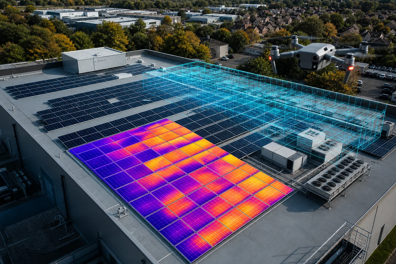
Begin with a high‑resolution drone survey of the roof and the panels. The drone captures orthomosaics that let you spot membrane tears, ponding, lifted clips and broken flashings in a single pass. A visual check also reveals soiling levels and any obvious shading from nearby structures.
Solar Surveys Ltd describes a typical commercial roof inspection as an “engineer‑reviewed condition assessment” that looks at surface condition, fixings, drainage and PV status. We follow the same checklist but add an IEC‑compliant layer: every image is geotagged, timestamped and linked to a panel‑by‑panel map.
Key things to record:
- Membrane integrity , note any lap‑seam separation or blistering.
- Fixing density , count the number of bolts per panel row and flag any missing or corroded fasteners.
- Drainage performance , inspect gullies, down‑pipes and parapet drains for blockage.
- Panel condition , look for visible cracking, hot‑spot indicators, ballast displacement and frame integrity.
When you finish the visual pass, you should have a set of annotated images that show every defect on the roof surface and a short note on each PV module’s external condition.
Step 3: Carry Out Electrical Tests and Record Baseline Results
Electrical testing validates that the array is safe to operate and that performance matches design expectations. The core tests are:
- Open‑circuit voltage (Voc) and short‑circuit current (Isc) at the string level.
- Insulation resistance between conductors and earth.
- Ground continuity checks on the rack and inverter chassis.
- Leakage current measurement to catch moisture‑induced faults.
These measurements are taken with a calibrated multimeter or a dedicated PV test set. Record the readings in a spreadsheet that mirrors the panel layout from your 3‑D model. This creates a baseline you can compare against future inspections.
IEC 62446‑3 mandates that test data be logged under stable irradiance (≥600 W/m²) and wind below 5 m/s (Wikipedia). If conditions drift, pause the test and wait for a clear sky.
Below is a simple table that summarises the most common electrical checks and the purpose they serve.
By now you should have a clean set of electrical numbers that match the visual map. Any out‑of‑tolerance reading flags a panel or wiring issue that needs deeper investigation.
Step 4: Use Solar Thermography to Locate Defects
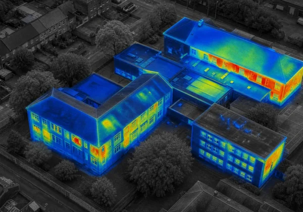
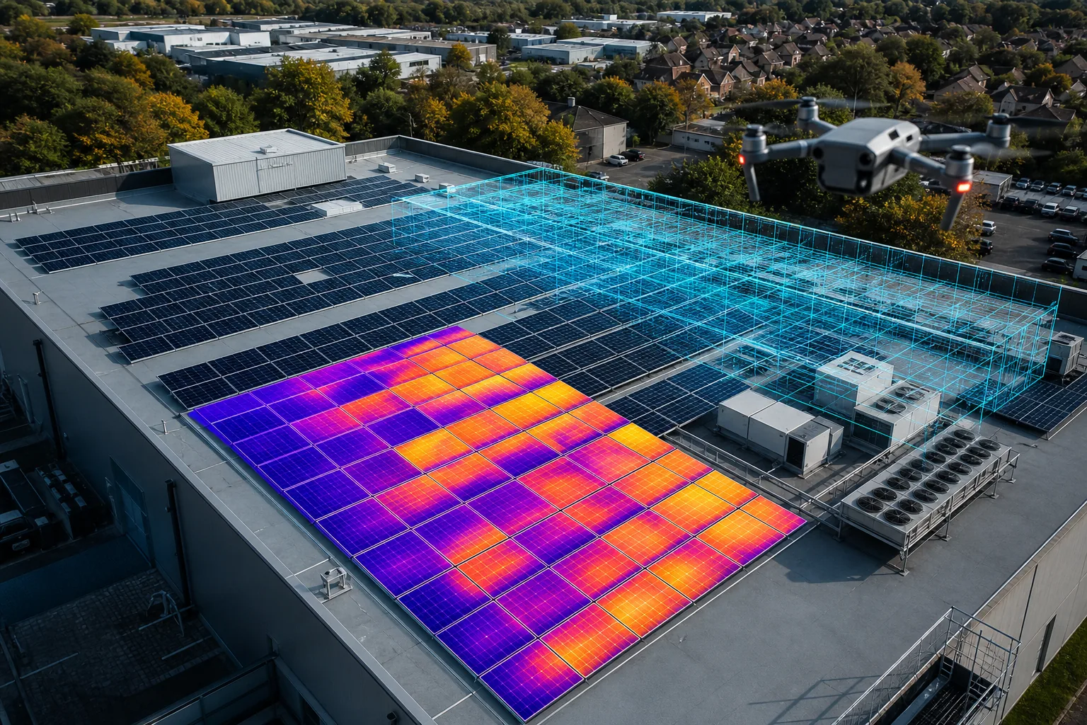
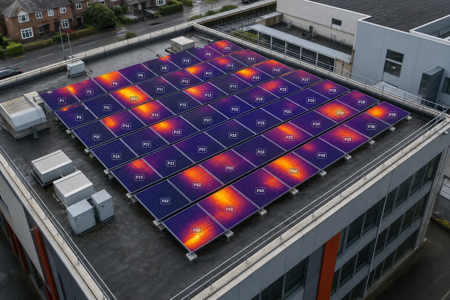
Thermal imaging reveals hidden faults that a visual check can’t see. A hotspot shows up as a bright spot on the thermogram because a defective cell or connector forces current to flow through a higher‑resistance path, turning electricity into heat.
Visual Perspectives Limited provides radiometric thermal data that meets IEC 62446‑3’s pixel‑density rule , each cell must be covered by at least 5 × 5 pixels. Our drones carry radiometric thermal cameras calibrated to 0.85‑0.90 emissivity for glass‑covered PV cells.
Typical thermography workflow:
- Check weather: clear sky, irradiance ≥ 600 W/m², wind < 5 m/s.
- Set camera emissivity to 0.88 and perform a quick black‑body calibration.
- Fly the drone at an angle to minimise reflection, capturing overlapping passes across the array.
- Stitch the images into a geo‑referenced heat map.
- Mark any area where temperature exceeds the surrounding cells by more than 5 °C.
Hotspots can indicate cracked cells, failed bypass diodes or loose MC4 connectors. If a hotspot appears on a combiner box, the fault may be in the wiring rather than the module itself. Document each anomaly with panel ID, GPS coordinates and a temperature delta.
After you finish the thermal pass, you’ll have a heat‑map overlay that pinpoints exactly where the array is losing efficiency or posing a fire risk.
Step 5: Analyse Findings and Produce an Actionable Test Report
All data , visual photos, 3‑D models, electrical readings and thermograms , must be collated into a single IEC‑compliant report. Start with an executive summary that lists the most critical faults (red‑level) and their potential impact on performance or safety.
Then add a fault matrix. Use colour coding: red for safety‑critical (e.g., hot‑spot > 30 °C), orange for high‑impact performance loss (5‑30 °C delta), yellow for moderate issues, and green for minor cosmetic concerns. For each entry, include:
- Panel or component ID.
- Location on the 3‑D model (link to the orthomosaic).
- Temperature delta or electrical deviation.
- Recommended remedial action and an estimated cost tier.
Visual Perspectives’ reporting format exports to CSV, shapefile and IFC, making it easy to feed the data into an asset‑management system. The report also carries the IEC 62446‑3 compliance stamp, which insurers and warranty providers accept without question.
Before you hand the report to the client, run a quick quality check: ensure every image has a timestamp, verify that all test values are within the IEC limits, and confirm that the safety section lists the grounding resistance and isolation test results.
Once the report is signed off, the client can use it to plan repairs, schedule maintenance or submit evidence for PSDS Phase 4 funding.
FAQ
What is the first thing I should do before starting solar PV testing?
The first step is to define the testing scope and put safety controls in place. That means deciding whether you need a full IEC 62446‑3 compliance check or a quicker visual audit, and making sure all personnel have the right protective equipment and that the drone operation is covered by a CAA Category 2 authorisation.
How often should a commercial solar array be thermographically inspected?
Annual thermal inspections are the industry norm for the first three years of operation, then every two years thereafter, unless the site is in a harsh environment where six‑month intervals are advisable.
Do I need specialised equipment to perform the electrical tests?
Yes, you need a calibrated PV test set or a multimeter that can measure high voltage and low leakage currents. The equipment must be capable of logging data under the irradiance and wind limits set out in IEC 62446‑3.
Can I use a handheld thermal camera instead of a drone?
A handheld camera can catch obvious hotspots, but it won’t give the full‑roof coverage, geotagging or 3‑D context that a drone provides. For large commercial arrays, a drone‑based survey is far more efficient and meets IEC compliance.
What does an IEC 62446‑3 compliant report look like?
An IEC‑compliant report includes a weather log, irradiance level, timestamped RGB and thermal orthomosaics, a table of electrical test results, a colour‑coded fault matrix and a signed engineer’s declaration that the inspection meets all standard requirements.
How do I turn the test results into a maintenance plan?
Start by categorising each fault by risk level, then assign an action owner and a target date. Feed the list into your asset‑management software so you can track progress, budget for repairs and demonstrate compliance to insurers or funding bodies.
Ready to get a compliant, data‑rich inspection? Best IEC 62446 Commercial Solar PV Thermography Services … shows how our end‑to‑end workflow meets every requirement.
Need a quick reference on thermal inspection methods? Top 8 Solar Panel Thermal Inspection Methods for … breaks the process down into bite‑size steps you can follow on any site.
For a full safety checklist and sample report template, download our guide How to Carry Out Solar Panel Testing Safely. It walks you through each stage, from planning to sign‑off.
Conclusion
Visual Perspectives provides the only UK service that combines full IEC 62446‑3 certification, high‑resolution thermal imaging and 3‑D roof mapping in one package, so you get reliable data and a compliant report in just three days. Contact us to schedule your next solar PV testing campaign and keep your assets running safely and efficiently.