Solar PV faults often develop without a clear warning. A system may still produce power while one panel, connector, bypass diode or inverter runs outside normal limits. Good solar panel fault finding starts with records, not guesswork, then moves through safe checks and targeted tests.
This method suits commercial roofs, schools, NHS estates and other public buildings. It also shows when a qualified electrician or independent thermal survey is needed.
Step 1: Confirm the Symptoms and Collect System Records
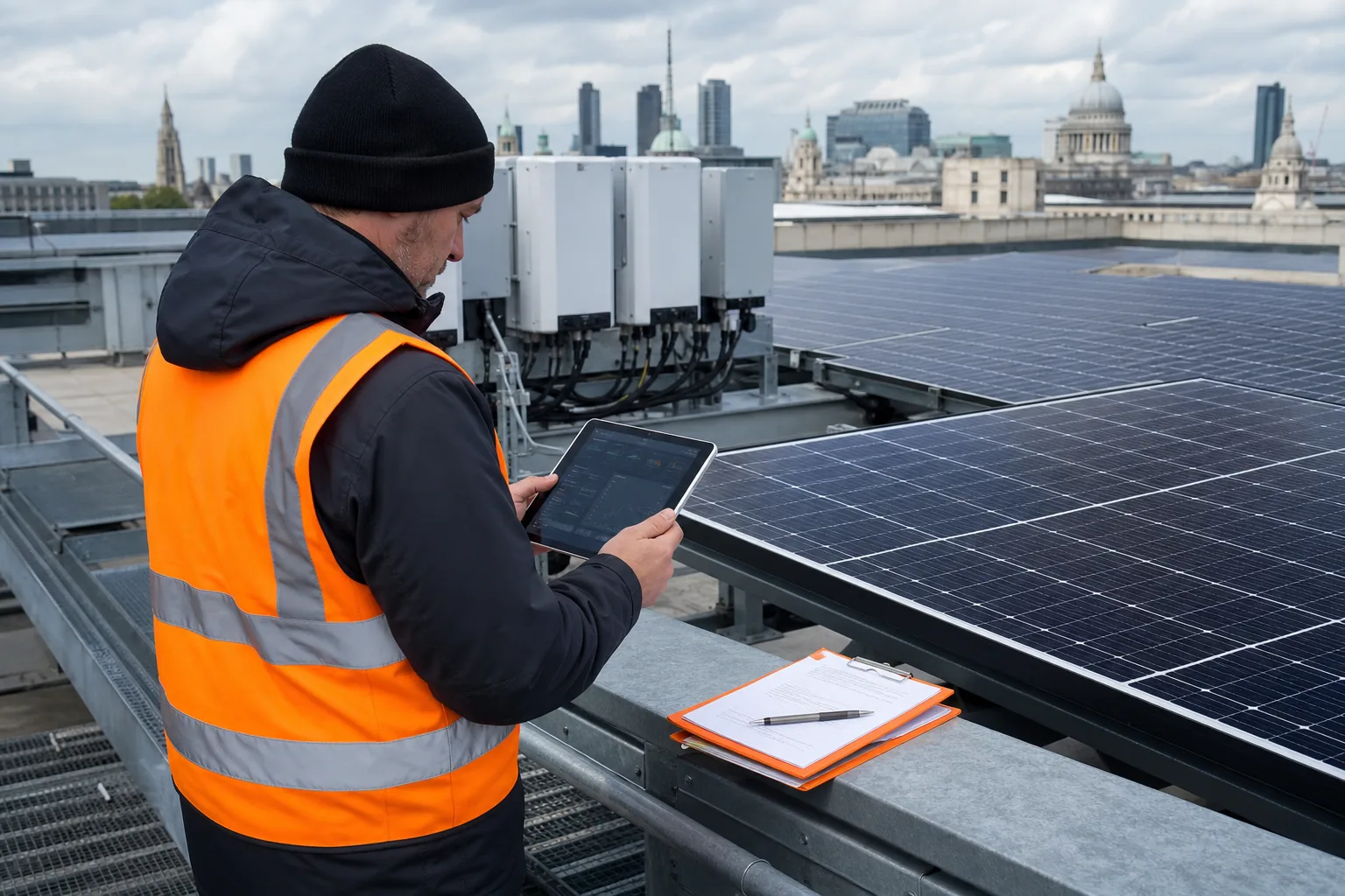
The goal is to define what changed before anyone touches the PV system. Solar panel fault finding becomes much faster when you can compare the current condition with a known baseline.
Start with the inverter display or monitoring portal. Record the date and time of each alarm. Note whether the fault affects the whole site, one inverter or one string. A sudden loss points to a different cause from a slow fall in generation over several weeks.
Gather the commissioning pack before arranging a roof visit. Look for the array layout, panel count, inverter schedule, string plan and rated capacity. Add past inspection reports, warranty records and recent cleaning or building work.
Write down the conditions when the problem appeared. Include weather, shading from temporary plant, grid outages and any planned shutdown. Check whether the monitoring data feed is complete. A missing data stream can look like a generation fault.
Inverter fault codes can narrow the first line of enquiry, but they rarely prove which physical part has failed. Use the manufacturer’s code description and record the exact wording rather than relying on memory. A qualified person should handle any live electrical diagnosis.
For a wider review of the early signs, our solar panel monitoring guidance explains how to set a baseline and link alerts to maintenance records.
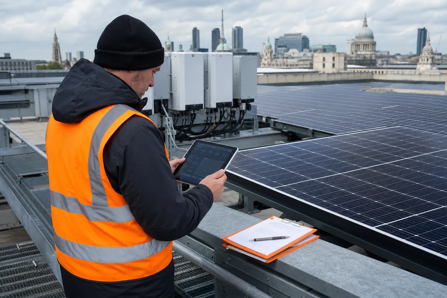
By now you should have a clear symptom statement, a system layout and the records needed for a safe inspection.
Step 2: Carry Out Safe Visual and Roof-Level Checks
The goal is to find obvious damage without creating a new safety risk. Visual checks remain useful, but they only show what the naked eye can see.
Begin from ground level. Look for panels that appear cracked, displaced or unusually dirty. Check for new shade from plant, scaffolding or nearby construction. Compare the array with older photographs if those records exist.
Do not walk across a commercial roof just to reach a panel. Roof membranes may be fragile, and skylights can be hard to spot from above. Follow the site’s roof access plan. Keep clear of edges, fragile surfaces and equipment that has not been made safe.
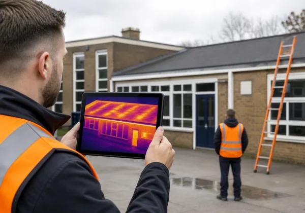
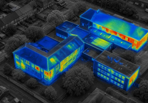
A drone roof survey can inspect difficult areas without sending staff across the array. It can capture RGB images, which show physical condition, while a thermal sensor records temperature differences. Visual Perspectives Limited provides managed drone inspections across the UK, with high-resolution mapping that can place a defect on the correct roof area.
At roof level, check the parts that often explain a visible change:
- panel glass, frames and mounting clips;
- cables that are loose, unsupported or rubbing against a surface;
- junction boxes and connectors;
- bird fouling, leaf build-up or heavy soiling;
- water ponding near roof penetrations or plant.
Do not clean or move anything before it has been recorded. A repair team needs to know the condition that existed when the fault was found. Take matching overview and close images. Mark each finding against the roof plan.
A visual check may show a cracked module or poor cable route. It cannot confirm a hidden cell fault or a hot connector. That is where electrical testing or thermography earns its place.
Our guide to common solar panel problems can help you match visible symptoms with the next inspection question.
By now you should have a marked-up visual record, with unsafe areas excluded from the work plan. You’ll be in good hands when the inspection follows the site risk assessment rather than a rushed roof walk.
Step 3: Test the Electrical System Methodically
The goal is to confirm whether the symptom sits in the DC array, the inverter, the AC side or the monitoring system. Electrical testing must be done by a suitably competent person because PV strings can remain energised in daylight.
Start with the least intrusive checks. Confirm the inverter status. Check whether the AC supply is present. Then compare the reported string values with the array plan and the readings from similar strings under similar conditions.
Never remove covers or disconnect a string because a web page suggests it. Follow the system design, isolation procedure and equipment instructions. Use suitable test gear with the right rating. Where the installation is part of a larger public estate, record who carried out each test and which instrument was used.
A methodical electrical check may include:
- DC string voltage compared with the expected panel count;
- string current under stable operating conditions;
- insulation resistance where the test method and system design allow it;
- continuity and polarity checks;
- AC output and inverter status;
- connector, isolator and combiner-box condition.
String voltage can expose an open circuit or a missing module. Low current may point to shade, soiling, a damaged cell or a connection problem. A result outside expectation is a prompt for further checks, not proof of one fault.
Thermal evidence helps link a reading to a physical location. For example, a low string current with one warm connector suggests a different repair from a low reading paired with an evenly cold section of panels.
Keep the test record beside the monitoring data. Note irradiance if measured, ambient conditions, inverter load and the time of each reading. Do not compare figures taken in very different conditions as if they were equal.
The solar panel testing guidance from Visual Perspectives Limited explains how visual checks, electrical tests and IEC 62446-3 reporting fit together.
Electrical testing can confirm that a circuit behaves differently. It may still leave the exact panel or connector unknown. Use the next step when access is difficult or the fault is hidden.
Step 4: Use Thermal Imaging to Locate Hidden PV Faults
The goal is to locate heat patterns that point to electrical or physical defects. Thermal imaging shows what the naked eye can’t see, but only when the survey conditions support a reliable result.
A healthy operating module usually has a fairly even thermal pattern. A local hot area can point to a cracked cell, high resistance, a loose connector or a failing bypass diode. A broad warm section may indicate a diode issue or another string-level problem. Cold areas can relate to shade, disconnection or reduced current.
Thermal imaging is not a colour-based pass or fail test. Reflections, cloud, wind, rain and recent shade can all change the image. The person interpreting the data must compare the suspect area with nearby modules under similar load and irradiance.
For a valid survey, plan the flight around the array’s operating state. Record the weather and light conditions. Avoid scanning after rain or through rapidly changing cloud. The camera must resolve enough detail to assess the cells and relevant components.
Thermography should cover more than the panel faces. Junction boxes, combiner boxes, isolators, connectors and inverters can also show abnormal heat. Skipping those parts leaves a gap in the fault record.
Visual Perspectives Limited combines radiometric thermal images with RGB capture and 3D mapping. That means a warm area can be tied to a panel position, roof reference or component rather than left as an unclear image in a large folder. The company’s published service information describes reporting aligned with IEC 62446-3 and inspection of commercial roofs and public buildings, as set out in its commercial PV thermography service information.
During review, record the panel or string reference, the measured temperature difference and the matching RGB view. Flag possible false positives for a repeat scan under stable conditions. Do not recommend a panel replacement from one uncertain thermal image.

By now you should know which anomalies need electrical confirmation, repair planning or a repeat scan. The next step turns those findings into a record that other people can act on.
Step 5: Verify, Classify and Report the Findings
The goal is to turn inspection evidence into a clear work plan. A useful fault report tells a facilities manager what was found, where it is, how certain the finding is and what should happen next.
Start with an executive summary. State whether the array was operating during the survey. Include the inspection date, weather conditions and method used. Say if the work covered the full array or only selected areas.
Each defect entry should contain:
- roof, array, inverter, string or panel reference;
- matching RGB and thermal images;
- temperature difference or electrical reading, where relevant;
- likely cause, with uncertainty stated clearly;
- risk rating and recommended action;
- follow-up requirement and suggested priority.
Separate safety concerns from performance concerns. A hot connector may need urgent attention even when total generation still looks acceptable. Soiling may reduce output without indicating an electrical failure. A damaged roof membrane may need a building repair team rather than a solar installer.
Use the report inside the asset management system. Attach the roof plan and inspection images to the work order. Add the repair date and carry out a post-repair check. A second thermal scan can show whether the abnormal pattern has gone.
For public-sector estates, this record can support warranty discussions, insurance review, planned maintenance and decarbonisation decisions. Independent evidence also helps when the installer and asset owner disagree about the cause of a fault.
Visual Perspectives Limited can combine solar thermography with wider roof and building diagnostics. That matters when the PV issue sits beside moisture, access or roof-condition concerns. A single mapped survey can give the project team a more useful handoff than separate, unreferenced photographs.
Keep the final report factual. Do not describe an anomaly as a confirmed failure until the supporting evidence justifies that wording. A clear limitation is more useful than false certainty.
By now you should have a ranked fault list, an evidence pack and a follow-up plan. That is the point at which solar panel fault finding becomes useful for day-to-day estate management.
FAQ: Solar Panel Fault Finding
What is the first step in solar panel fault finding?
The first step is to confirm the symptom from monitoring data, inverter records and the array plan. Record when the change began and whether it affects one string or the whole site. This avoids testing the wrong part of the system and gives the inspector a clear starting point.
Is specialist help needed for solar panel testing?
You can carry out safe ground-level observations, but live electrical tests should be left to a suitably competent person. PV strings can produce hazardous DC voltage in daylight. Do not remove covers, disconnect cables or open combiner boxes without the right training, method statement and test equipment.
What faults can thermal imaging find?
Solar thermography can locate abnormal heat linked to damaged cells, high-resistance connections, bypass diode problems and some string faults. It can also show patterns caused by shade or soiling. The image needs the right weather and load conditions, plus trained interpretation, before it supports a repair decision.
When is a drone survey better than a roof inspection?
A drone survey is useful when the roof is large, fragile, steep or difficult to access safely. It can capture overview images without sending staff across the array. A close physical inspection may still be needed for repair or confirmation, but aerial data can show where that work should focus.
How often should solar PV systems be inspected?
Inspection frequency depends on the system, roof environment, insurance terms and operating history. Commercial owners often use routine visual review with planned thermal inspection, then increase checks after faults, severe weather or building work. Set the interval through the asset risk plan rather than using one schedule for every roof.
Conclusion
Use records first, then progress through safe visual checks, qualified electrical testing and thermal imaging when the fault remains hidden. For large or hard-to-access sites, Visual Perspectives Limited can provide independent drone-based PV thermography with mapped reporting. The next step is to gather your monitoring history and commissioning drawings before booking an inspection.